MULTI VRF-Ⅱ INDOOR UNIT SERVICE MANUAL EUROPEAN/LATIN AMETICA (R410A)
49
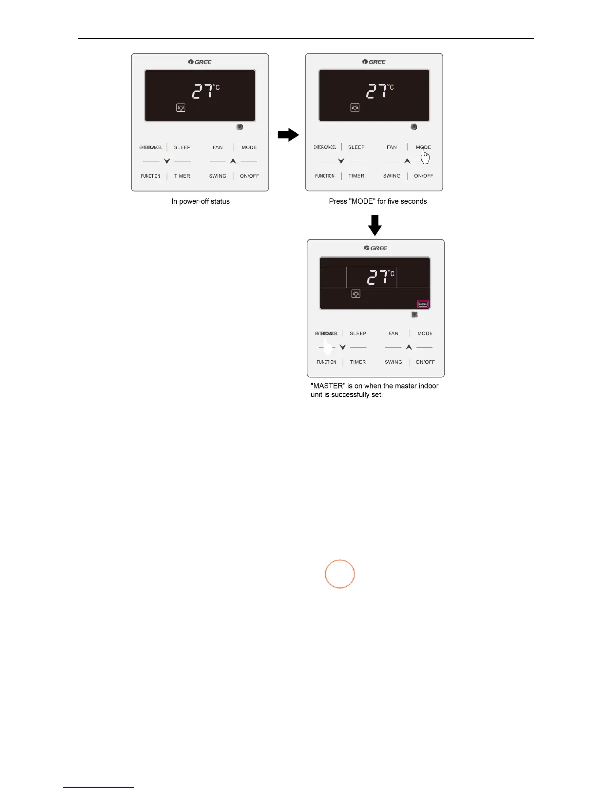
Method 2:
Step 1: Press and hold the “FUNCTION” button for five seconds in power-on or power-off status to enter
the parameter query interface.
Step 2: Press and hold the “FUNCTION” button for five seconds in "C00" status to enter the parameter
setting interface.
Step 3: Press “▲” or “▼” to switch level 2 parameter codes till “P10” is displayed on the temperature area.
Step 4: Press the “MODE” button to set the parameter to "01" and then Press the “ENTER” button. If the
setting is successful, "MASTER" on the wired controller will be on.
Master IDU Display
① For IDUs connected with wired controllers, "MASTER" on the wired controller connected with the
master IDU will be on.
② For IDUs embedded or connected with LED panels, the operation LED on the LED panel of the
master IDU will blink three times.
Note: After the master IDU is successfully set, stick the “
” flag to the wired controller or unit panel
for convenience of user operation and engineering maintenance. This flag is placed in the package bag
of the ODU.
5.1.2 Project number Query and Settings
(1) Project number query of a single IDU
Press and hold the “FUNCTION” button for five seconds in power-on or power-off status to enter the
parameter query interface "C00". The timer area of the wired controller displays the project number of the
current IDU. Synchronously, the double-eight digital LED of the IDU embedded or connected with an LED
panel displays its own project number. If the current wired controller works in one-to-many mode, the
timer area displays the IDU that has the minimum project number.
 Loading...