MULTI VRF-Ⅱ INDOOR UNIT SERVICE MANUAL EUROPEAN/LATIN AMETICA (R410A)
53
and hold the “FUNCTION” button for another five seconds to enter the wired controller parameter
setting interface. The temperature area displays “P00”.
(2) Select a parameter code by pressing “ ” or “ ”. Press the “MODE” button to switch to parameter
value settings. The parameter value blinks. Adjust the parameter value by pressing “ ” or “ ” and
then press the “ENTER/CANCEL” button to complete settings.
(3) Press the “ENTER/CANCEL” button to return to the upper-level menu till quitting parameter settings.
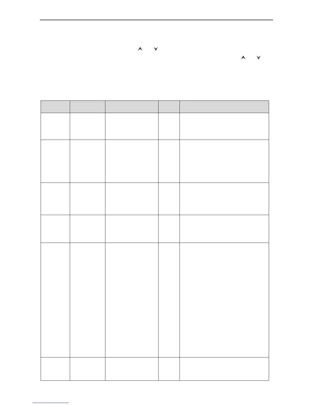
(4) The user parameter setting list is as follows:
Table 2.2 User Parameter Setting List
00: does not change the
master/slave status of
the current IDU
01: sets the current IDU
to master IDU
After the IDU connected
with the current wired controller is
successfully set to master IDU, "MASTER"
on the wired controller is on.
Infrared
connection
settings of
wired controller
This setting can only be enabled through
the master wired controller.
When the infrared remote receiving
function of the wired controller is disabled,
neither the master nor slave wired
controller can receive remote signals. The
wired controllers can only be operated by
pressing.
Wired
controller
address
settings
01: master wired
controller
02: slave wired controller
When two wired controllers simultaneously
control one or more IDUs, the two wired
controllers should use different addresses.
The slave wired controller (address: 02)
does not have the unit parameter setting
function except its own address settings.
Group-
controlled IDU
quantity
settings
01-16: number of indoor
units
This value is set based on the number of
connected IDUs.
If the current value is inconsistent with the
actual number of group-controlled IDUs, an
“L9” fault may occur.
Static pressure
settings for
indoor fan
Type 2:
01.02.03.04.05.06.07.08
.09
After identifying the IDU type, the wired
controller only displays the available
static pressure levels.
1) The static pressure levels fall into five
levels and nine levels for VRF IDUs.
The wired controller only displays the
static pressure levels matched with the
identified IDU type.
2) When the HBS network consists of IDUs
with both five and nine static pressure
levels, the wired controller displays nine
adjustable static pressure levels
according to the maximum control
principle. If the static pressure levels
received by the IDU from the wired
controller, remote controller, or remote
monitoring system exceed the setting
range, the limit value prevails.
3)During power-on and synchronization,
the setting value of static pressure
levels is determined by settings of the
IDU.
High-ceiling
installation
00: standard-ceiling
installation height
01: high-ceiling
installation height
 Loading...