100
DC Inverter Multi
VRF Service Manual
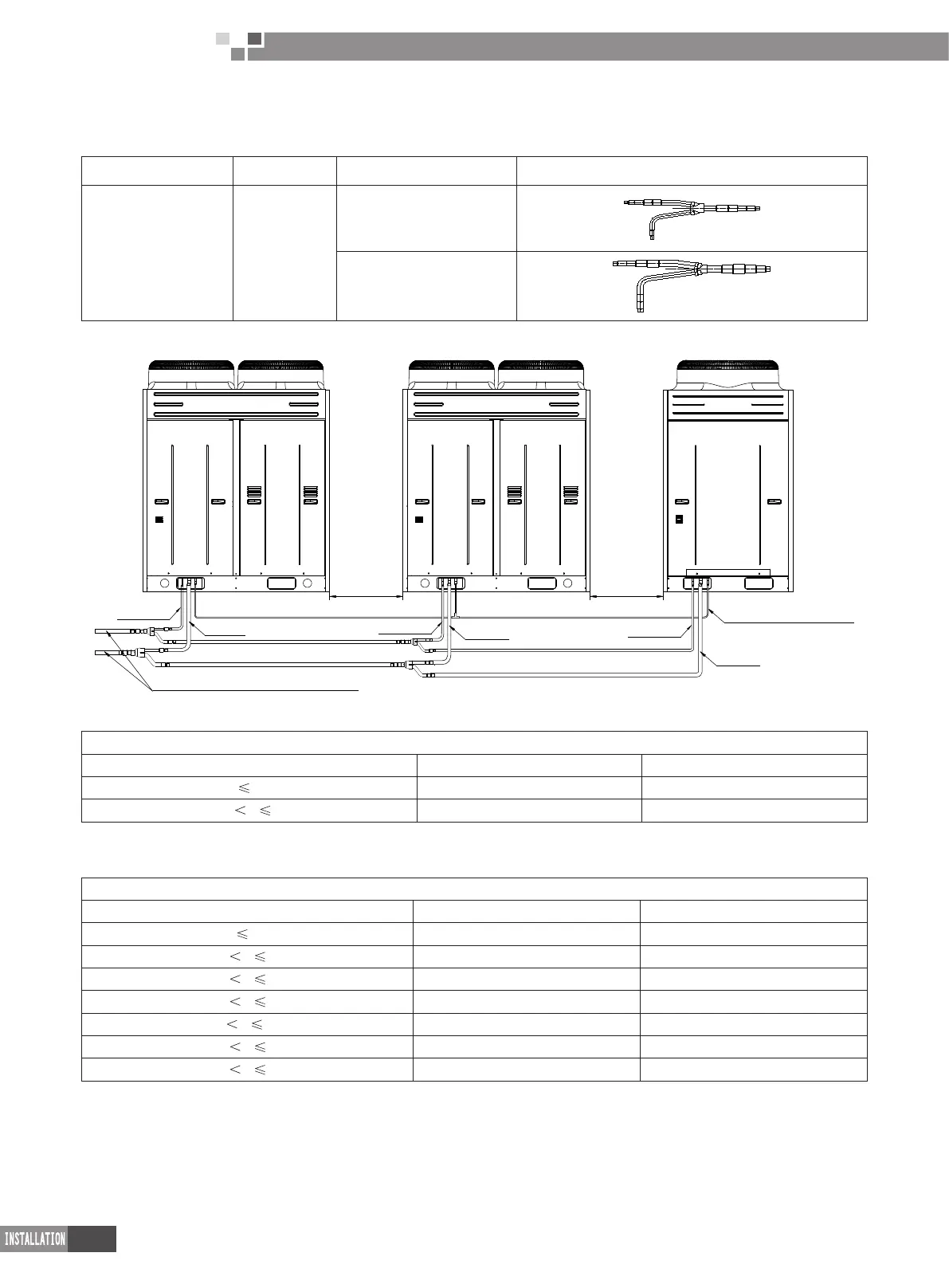
4�5 Selection of Refrigerant Piping between Outdoor Unit and Outdoor Unit ( for module unit)
4.5.1 Selection of components between module and module
Notes Model Name Illustration
Sub-assembly
corresponding to
outdoor module
ML01/A
ML01- Liquid pipe
ML01- Air pipe
4.5.2 Selection of pipe diameter between module and module
>30mm
>30mm
Pipe between outdoor unit and indoor unit
Pipe between outdoor unit and
connection sub-assembly
Liquid pipe
Liquid pipe
Gas pipe
Gas pipe
Liquid pipe
Gas pipe
4.5.2.1 Pipe diameter between outdoor unit and connection component
R410a refrigerant system
Single module capacity code C Gas pipe (mm/inch) Liquid pipe(mm/inch)
C
280 Φ22.2 Φ9.52
280
C 45 Φ28.6 Φ12.7
4.5.2.2 Pipe diameter between connection component of module and connection component of module
R410a refrigerant system
Sum of capacity code of upstream module C_ Gas pipe (mm/inch) Liquid pipe(mm/inch)
C
280 Φ22.2 Φ9.52
280
C 450 Φ28.6 Φ12.7
450
C 670 Φ28.6 Φ15.9
670
C 954 Φ34.9 Φ19.05
950
C 1350 Φ41.3 Φ19.05
1350
C 1600 Φ44.5 Φ22.2
1600
C 2100 Φ54.1 Φ25.4
4.5.2.3 Piping used for balancing lubricant
The oil balance pipe is connected by using Φ12.7 copper pipe. For three outdoor units arranged in parallel, one 3-way
joint having an inner diameter of Φ12.9 shall be used in the oil balance pipe.

 Loading...