DC Inverter Multi
VRF Service Manual
85
CONTROL
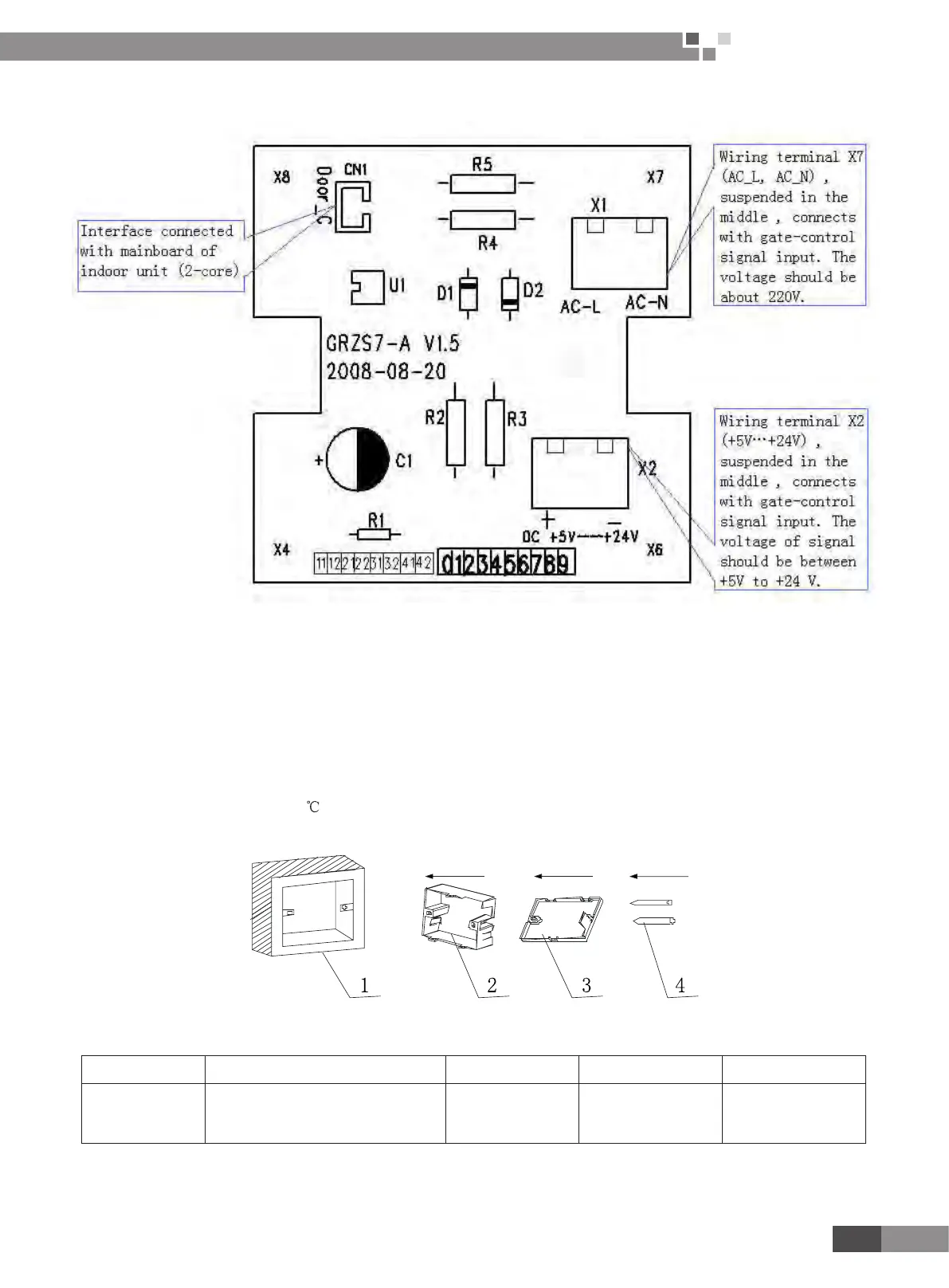
8�3 Detection Control Board Interface Sketch is shown in Fig�2:
Fig2: Detection Control Board Interface Sketch
The gate-control function can be realized after the detective interface of detection control board connects with
interface of gate-control card and signal interface of it connects with the mainboard.
8�4 Products Parameters
Model: MK03 gate controller
Working Voltage: AC 220-240V, 50HZ or DC +5V-+24V
Power: 1W
Working temperature: -10~48
8�5 Installation of Detection Control Board
Fig. 3 Installation Sketch of Detection Control Board
No. 1 2 3 4
Description
Base box of socket installed
in the wall , a hole with
( L×W×D)100mm×100mm×50mm
Bottom plate
of detection
control board
Front panel of detection
control board
Screw M4X25
Note: Detection control board with (L×W×H) 73.5mm×73.5mm×33.0mm

 Loading...