EasyManuals Logo

Gree GRH120DB-K6NA1A User Manual

Gree GRH120DB-K6NA1A
53 pages
To Next Page IconTo Next Page
To Previous Page IconTo Previous Page
Page #12 background imageLoading...
Page #12 background image
10
Technical Information
CAP.
WH
BU
S
BU
R
C3
INDOOR UNIT
OUTROOM
SENSOR
N14WAY
VALVE
4-WAY
4YV
N
COMP
AC-L
PE
BU
BN
YEGN
AP1
TUBE SENSOR
OUTDOOR
RT1
TUBE
SENSOR
RT2
MAIN BOARD
RT3
(20K) (15K)(20K)
(WH) (BK)
VT VT
K7
DISP1
T-SEN
MOTOR
IN_FAN
0
0
0
C
RD
COMP
COMP.
L
N
POWER
PE
M2
YEGN
MOTOR
OUT_FAN
C2
RD
BN
CAP.
M1
C1
RD
BN
CAP.
FAN
YEGN
PE
OFAN
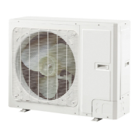
Outdoor Unit
These wiring diagrams are subject to change without notice; please refer to the one supplied with the unit.
600007064532

Questions and Answers:

Question and Answer IconNeed help?

Do you have a question about the Gree GRH120DB-K6NA1A and is the answer not in the manual?

Gree GRH120DB-K6NA1A Specifications

General IconGeneral
BrandGree
ModelGRH120DB-K6NA1A
CategoryAir Conditioner
LanguageEnglish

Related product manuals