96
Installation and Maintenance
Service Manual
Step Procedure
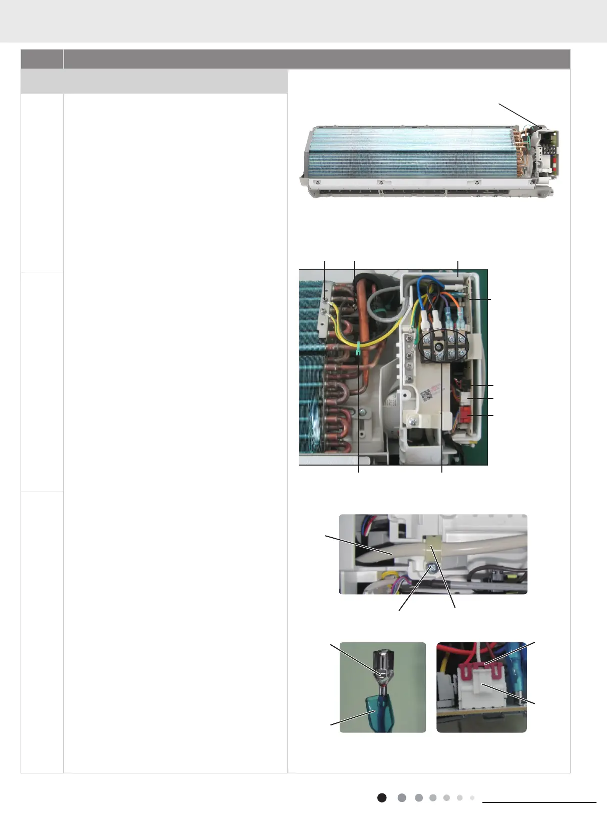
6. Remove electric box assy
a
Remove the screw xing electric box assy.
①
Cut off the wire binder and pull out the indoor tube
temperature sensor.
②
Screw off one grounding screw.
③
Remove the wiring terminals of healthing / UVC, up
& down swing, left & right swing.
④
Remove the electric box assy.
⑤
Screw off the screws that are locking each.
Rotate the electric box assy. Twist off the screws that
are locking the wire clip and loosen the power cord.
Remove the wiring terminal of power cord. Lift up the
main board and take it off.
Instruction:Some wiring terminal of this products is with
lock catch and other devices.The pulling method is as
below:
1.Remove the soft sheath for some terminals at first,
hold the circlip and then pull out the terminals,
2.Pull out the holder for some terminals at rst(holder
is not available for some wiring terminal).hold the
connector and then pull the terminal.
b
C
Screw
Main board
Grounding
screw
Indoor tube
temperature
sensor Electric box assy
Screw Wire clip
Circlip Holder
Connector
Soft sheath
Power cord
Terminal of healthing
/ UVC
Terminal of up &
down swing
Terminal of left &
right swing
ScrewsWire binder
 Loading...