24
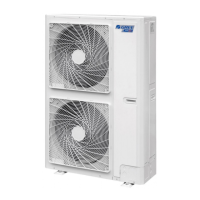
Condensing Unit
Service Manual
Bume
r
Solder
Downward facing
Side facing
Recommended methed
Upward facing
Figure 3-1-3
Uninsulated connecting pipes and connectors should be packed with sponge and tied with plastic adhesive
tapes.
(2). Vacuum-pumping and leak detection
Dismantle the bonnet of refrigerant valve and air valve.
Align with the center of piping and adequately tighten nuts of connecting pipes by hand
Tighten the nuts with a spanner.
Remove the one way valve cap of air valve.
Unscrew the spool of refrigerant valve for 1/4 turn with a socket head wrench, and at the same time push
up the spool of air valve with a screwdriver to let air give off.
Air exhaust continues for 15 seconds until coolant gas appears, immediately shut off one way valve and
tighten the valve cap.
Totally open the spool of refrigerant valve and air value (as shown in Figure 3-1-4)
One-Way Valve
Gas Valve
Liquid Valve
Valve Cap
Inner Hexagon
Spanner
Screwdriver
Valve Stem
Figure 3-1-4
Tighten the valve caps and use soapy water or a leak detector to check any leakage on indoor unit,
outdoor unit and connection parts of pipes.
Caution:
If conditions are allowed, a vacuum pump shall be used for drawing off air inside the system at a valve. Method
for creation of vacuum by using a vacuum pump is as follows:
Take out the nut cover of the inlet for refrigerant.
Connect the tube of the vacuum watch with the vacuum pump, having the low-pressure end linking to the
inlet for refrigerant. (As shown in Figure 3-1-5)
 Loading...