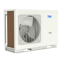
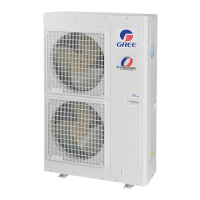
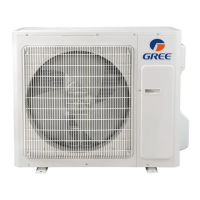
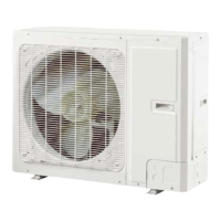
AIR-TO-WATER HEAT PUMP INSTALLATION
93
GRS-CQ12Pd/Na-M, GRS-CQ14Pd/Na-M, GRS-CQ16Pd/Na-M:
Error
indicating lamp
Running
indicating lamp
XT2
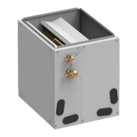
Inside Unit
Electric Box
L1 N
XT1
Water tank
LK
POWER
380 415V-3Ph-50Hz
Display
board
CN16 CN5
AP
2-way
valve1
2-way
valve2
3-way
valve1
3-way
valve2
Water-tank
temp sensor2
Water-tank
temp sensor1
Outdoor
Unit
PE
Main Baord
CN14
Remote air
temp sensor
Long-distance
monitor PC
CN7
Other thermal system
Water- out temp sensor
PE
Thermostat Thermostat
Power supply for Thermostat:If it is 230V AC,please
connect Terminal block(xt3) 21.22.23.24;If it is 24V
AC, please connect Terminal block(xt3) 25.26.27.28.
They are can not be connected as the same time.
If there is gate control function,
pull out the leading wire 50 on
terminal board
XT2)between19 and
20 and then connect the Gate-controller
Gate-controller
20 19
Specification:
1
Running indicating lamp(HL1) and Error indicating lamp (HL2) are connected or not on the basis of the
clients'demand.
2 Client water pump AC contactor(KM4) is back-up Pump for the future , so it is not be connect;
3 Leakage Switch
(LK) is necessary for additional installation, Please reference to
page 10 4.3 Electrical Data
L2 L3
L1 L2 L3
N
29 30 31
XT2
BKBN
BU
YEGN
PE

 Loading...

