Do you have a question about the Gree FLEXX36HP230V1AO and is the answer not in the manual?
Provides essential safety guidelines and warnings for proper usage of the air conditioner.
Details prohibited actions, warnings, and notices for safe maintenance procedures.
Outlines prohibited actions, warnings, and notices for safe operation of the unit.
Details outdoor and indoor unit models, their capacities, power supply, and product codes.
Provides electrical specifications including power supply and circuit breaker/fuse capacities for different models.
Explains the operational logic for cooling and heating cycles.
Details compressor, EXV, fan, and valve control mechanisms, including special and protection controls.
Covers dip switch settings for capacity, defrost mode, operating mode, and fan speed.
Details forced defrost, refrigerant recovery, forced operation, and thermostat functions.
Provides electrical diagrams for outdoor and indoor unit wiring.
Details the interfaces and connections on the indoor unit mainboard.
Lists all error codes, their descriptions, and potential causes for system malfunctions.
Diagnoses and provides solutions for E1 error (Compressor High Pressure Protection).
Troubleshooting for E3 error, covering low pressure and refrigerant issues.
Addresses E4 error related to high compressor discharge temperature and its causes.
Details troubleshooting steps for F2 error, indicating a condenser temperature sensor issue.
Troubleshooting guide for F3 error, related to the outdoor ambient temperature sensor.
Provides troubleshooting for F4 error, concerning the discharge temperature sensor.
Troubleshooting steps for F6 error, related to ODU tube temperature sensor malfunctions.
Guides on resolving EE error, indicating a problem with the ODU memory chip.
Troubleshooting for H4 error, related to system overload conditions.
Troubleshooting steps for H5 error, indicating IPM module protection.
Details troubleshooting for H6 error, related to the DC fan malfunction.
Troubleshooting guide for H7 error, concerning driver out-of-step protection.
Troubleshooting for HC error, related to PFC protection.
Guides on resolving Lc error, indicating inverter compressor startup failure.
Troubleshooting steps for P0 error, related to driver reset protection.
Troubleshooting for P5 error, related to compressor over-current.
Troubleshooting guide for P6 error, concerning communication issues.
Troubleshooting for P7 error, related to driver module sensor malfunctions.
Guides on resolving P8 error, indicating driver module high temperature protection.
Troubleshooting steps for PA error, related to AC current protection.
Troubleshooting for Pc error, indicating driver current error.
Troubleshooting guide for PL error, concerning bus low-voltage protection.
Troubleshooting for PH error, related to bus high-voltage protection.
Troubleshooting steps for PU error, related to charge loop errors.
Guides on resolving ee error, indicating a drive memory chip issue.
Troubleshooting for e1 error, concerning high pressure sensor malfunctions.
Troubleshooting steps for C4 error, related to ODU jumper cap issues.
Addresses common problems like unit not running or poor cooling/heating effects.
Illustrates the overall system diagram, including major components and refrigerant flow.
Detailed steps for performing vacuum pumping on connection pipes.
Step-by-step procedure for charging refrigerant into the system.
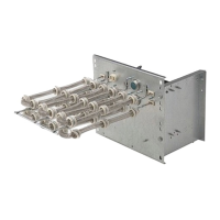
Instructions for replacing the thermostat unit.
Comprehensive guide for diagnosing and replacing the compressor.
Describes the removal procedures for major components of the Outdoor Unit (ODU).
Describes the removal procedures for major components of the Indoor Unit (IDU).
Exploded views and parts lists for the Outdoor Unit (ODU) models.
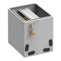
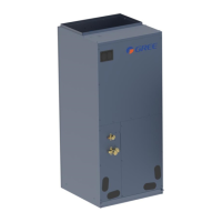
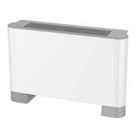
Exploded views and parts lists for Indoor Unit (IDU) models.
Provides voltage lists correlating resistance and temperature for 15K, 20K, and 50K sensors.
Table showing refrigerant R410A temperature and pressure values.
Lists the necessary tools for operating and maintaining the unit.
| Cooling Capacity | 36000 BTU/h |
|---|---|
| Heating Capacity | 36000 BTU/h |
| Refrigerant | R410A |
| HSPF Rating | 10 |
| Phase | 1 |
| Voltage | 208-230V |