Do you have a question about the Gree VERSATI SERIES and is the answer not in the manual?
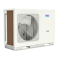
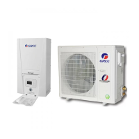
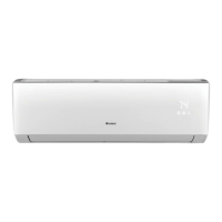
Lists main unit models, capacities, power supplies, and appearance details.
Details the naming convention and components of the main unit and water tank.
Explains the operational modes like cooling, heating, and water heating.
Provides technical specifications and performance data at rated conditions.
Illustrates the refrigerant and water piping connections for the system.
Outlines the sequence of operations for cooling, heating, and water heating modes.
Details the core control logic, including defrosting and anti-freezing operations.
Describes the features, dimensions, and operation of the wired controller interface.
Provides guidance on selecting installation positions for outdoor, indoor, and water tank units.
Presents dimensional drawings and installation guidelines for outdoor and indoor units.
Explains how to adjust expansion vessel pressure based on system volume and height.
Details the process for connecting refrigerant and water pipelines.
Covers general safety and compliance for electrical wiring.
Identifies components and their functions on the Printed Circuit Board.
Presents detailed wiring diagrams for various unit configurations.
Lists all error codes, their causes, and how to resolve them.
Provides visual guides for diagnosing and fixing common system issues.
Guides for diagnosing issues related to the unit's drive system and protections.
Provides exploded views and part identification for the outdoor unit.
Provides exploded views and part identification for the indoor unit.
Provides exploded views and part identification for the water tank.
| Refrigerant | R410A |
|---|---|
| Type | Air to Water |
| Power Supply | 220-240V, 50Hz |
| Heating Capacity Range | 4kW - 16kW |
| Water Outlet Temperature (Heating) | 55°C |
| Application | Underfloor heating, radiators, fan coils |
| Operating Temperature Range (Cooling) | 10°C to 46°C |
| Noise Level | 45-55 dB(A) |