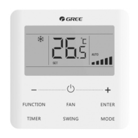
Wired Controller XK49
9
via the gate control card. As the following figures:
Figure 3.11 Connection fashion 2 of Wired Controller and Gate Control
Note:
①
Wired controller 2 in figure 3.11 can be set as master controller or slave
controller;
②
Wired controller 1 in figure 3.11 can be model XK49 or other models.
4. Power input of gate control card insertion/removal device supported by wired
controller: AC 100-240V~50/60Hz, DC 5~24V. In practice, connect the gate control
output power cord with the corresponding power supply interface of wired controller
according to the type of output power of gate-control device (Please refer to 3.1.4
Installation for wire connection of specific interface). Wired controller will judge the
placing and absence of card by detecting the power supply of gate-control device. The
detecting process is as follow:
Inserting or removing the gate control card is like connecting or disconnecting
power of the gate control device. When the card is inserted, the device supplies power
AC100-240V/DC5-24V to wired controller which identifies card insertion. When the card
is removed, the device stops supplying power AC100-240V/DC5-24V to wired
controller which identifies card removal. Figure 3.12 and figure 3.13 demonstrate wired
controller connecting gate control power of AC100-240V or DC5-24V:
Figure 3.12 Wired Controller Connecting to Gate Control AC100-240V