Energy Core Ventilator2
®
Table of Contents
Unit Overview . . . . . . . . . . . . . . . . . . . . 2
Receiving, Handling and Storage . . . . . . . . . 3
Installation
Outdoor and Indoor Mounting Options . . . . . . . 4
Dimensional Data and Weights . . . . . . . . . . . 4
Service Clearances . . . . . . . . . . . . . . . . . 5
Access Panel Locations . . . . . . . . . . . . . . . 5
Handling . . . . . . . . . . . . . . . . . . . . . . . 6
Lifting . . . . . . . . . . . . . . . . . . . . . . . . 6
Roof Curb Mounting. . . . . . . . . . . . . . . . . 7
Curb Outside Dimensions and Weights . . . . . . . 7
Ductwork Connections . . . . . . . . . . . . . . . 8
Rail Mounting / Layout . . . . . . . . . . . . . . . 8
Electrical Information
General Electrical Information . . . . . . . . . . . . 9
Control Center Components . . . . . . . . . . . .10
Optional Accessory Wiring Schematics. . . . . 10-11
Unit Overview
Basic Unit . . . . . . . . . . . . . . . . . . . . . .11
Optional Component Overview
Economizer . . . . . . . . . . . . . . . . . . . . .12
Frost Control. . . . . . . . . . . . . . . . . . . . .12
Variable Frequency Drive . . . . . . . . . . . . . .12
CO
2
Sensor . . . . . . . . . . . . . . . . . . . . .12
Dirty Filter Switch . . . . . . . . . . . . . . . . . .12
Start-Up
General . . . . . . . . . . . . . . . . . . . . . . .13
Pre Start-Up Checklist . . . . . . . . . . . . . . .13
Special Tools Required . . . . . . . . . . . . . . .13
Start-Up Checklist. . . . . . . . . . . . . . . . . .13
Optional Accessories Checklist . . . . . . . . . . .14
Start-Up Components
Fans . . . . . . . . . . . . . . . . . . . . . . . . .15
Fan Performance Modifications . . . . . . . . . . .15
Fan Belt Drives . . . . . . . . . . . . . . . . . . .15
Belt Drive Installation . . . . . . . . . . . . . . . .15
Direction of Fan Wheel Rotation . . . . . . . . . .15
Fan RPM. . . . . . . . . . . . . . . . . . . . . . .15
Optional Start-Up Components
Dirty Filter Switch . . . . . . . . . . . . . . . . . .16
Economizer . . . . . . . . . . . . . . . . . . . . .16
Frost Control. . . . . . . . . . . . . . . . . . . . .17
CO
2
Proportional Control . . . . . . . . . . . . . .17
Vari-Green® EC Motors . . . . . . . . . . . . . . .17
Variable Frequency Drives. . . . . . . . . . . . 18-20
Routine Maintenance . . . . . . . . . . . . . . 20-21
Troubleshooting
Economizer Alarms . . . . . . . . . . . . . . . . .22
Airflow . . . . . . . . . . . . . . . . . . . . . . . .23
Unit . . . . . . . . . . . . . . . . . . . . . . . 24-25
Maintenance Log . . . . . . . . . . . . . . . . 26-27
Our Commitment . . . . . . . . . . . . . Backcover
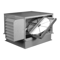
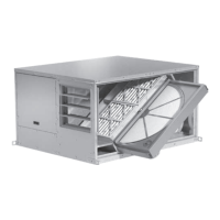
Unit Overview
Basic Unit
The unit is prewired such that when a call for outside air
is made (via field-supplied 24 VAC control signal wired
to unit control center), the supply and exhaust fans are
energized and optional motorized dampers open. The
unit is normally interlocked (24 volt) to the rooftop air
handler. When the rooftop air handler starts, the auxiliary
contactor in the air handler closes to start the unit.
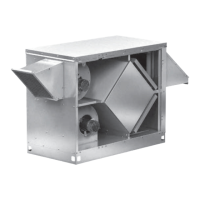
Summer Operation
Outdoor air is preconditioned (temperature and moisture
levels are decreased) by the transfer of energy from the
cooler, drier return air through the energy recovery core.
The preconditioned air is typically mixed with return air
going back to the air handler for final conditioning.
Winter Operation
Outdoor air is preconditioned (temperature and moisture
levels are increased) by the transfer of energy from
the warmer, more humid return air through the energy
recovery core. The preconditioned air is typically mixed
with return air going back to the air handler for final
conditioning.
Exhaust Air
Outdoor Air
95° F
125 grains/lb.
Supply Air
82° F
88 grains/lb.
Return Air
75° F
50% RH
Summer
Operation