Energy Core Ventilator 17
®
Frost Control Test Procedure
Timed Exhaust
1. Remove power from unit.
2. Jumper the temperature indicating sensor in the unit
control center. Thermostat controller has a pre-set
temperature of 35ºF.
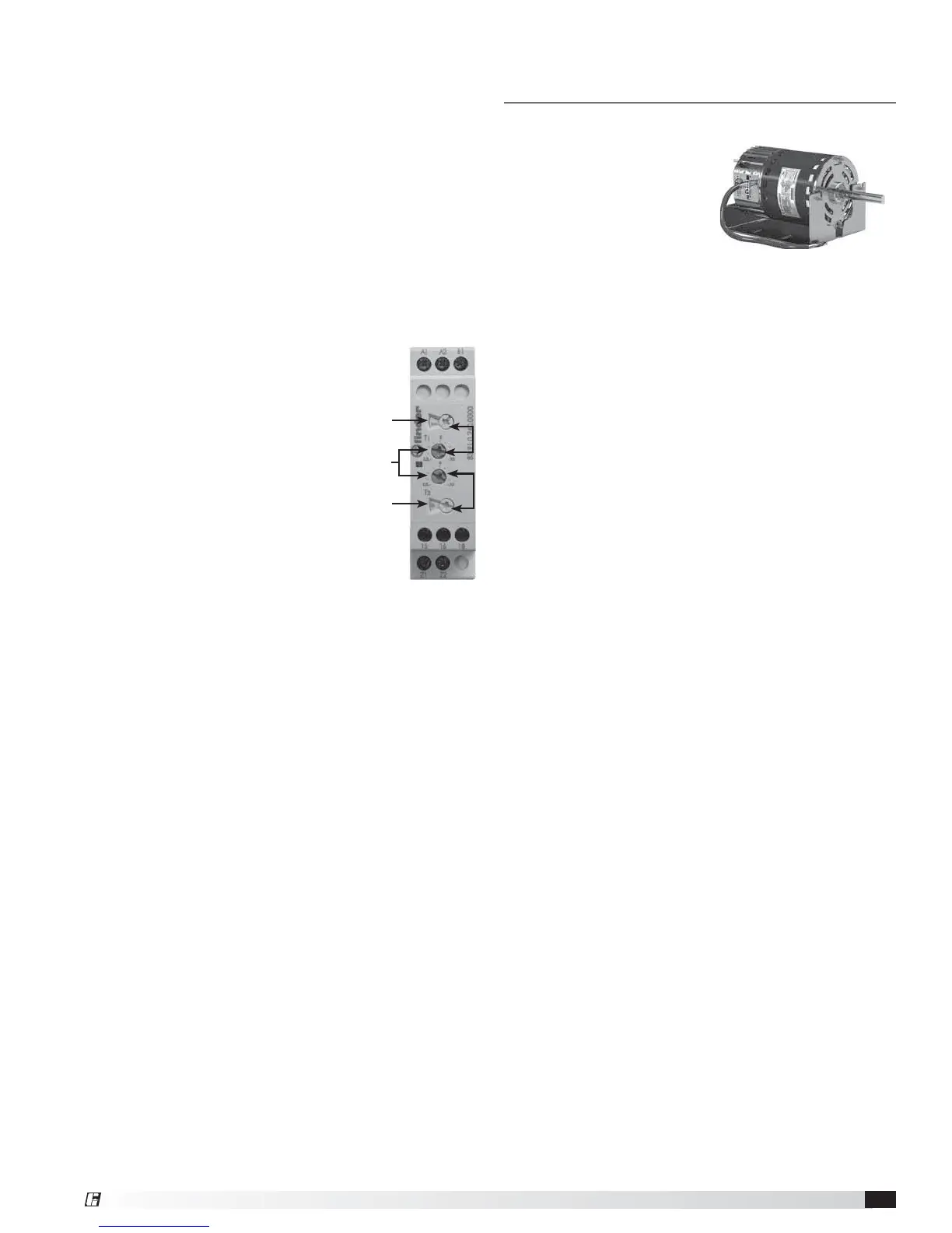
3. Set the frost control timer scale for T1 and T2 to 5m.
Set the timer settings for T1 and T2 to 30.
4. Add power to the unit. Blower should cycle on for 30
minutes, then turn off for 5 minutes.
5. Remove power from unit and remove jumpers that
were placed. Reset timer settings.
• T1 timer setting set to 5 and timer scale set to
10m for 5 minutes of blower off time.
• T2 timer setting set to 5 and
timer scale set to 1h for 30
minutes of blower on time.
Electric Preheat
1. Remove power from unit.
2. Place wire jumper between
terminal R and G.
3. Turn dial on the thermostat TS1
to highest temperature setting.
4. Apply power to unit. Preheater
should turn on.
5. Remove power from unit, if
applicable remove wire jumper placed between R
and terminal G, and turn dial on thermostat TS1 to
factory setting (35ºF).
CO
2
Proportional Control
Speed Controller
A carbon dioxide sensor is provided from the factory for
field mounting OR unit mounting in the space(s) being
served by the energy recovery unit.
The ECV-10-VG carbon dioxide sensor is wired to
the speed controller with default factory settings for
proportional control of 500 PPM or less CO
2
= 50% fan
speed and 1500 PPM or greater CO
2
= 100% fan speed.
The blower’s speed proportionally modulates between
500 and 1500 PPM CO
2
.
Variable Frequency Drive
The ECV-20 and ECV-30 are wired to the Variable
Frequency Drive (VFD). Refer to the Variable Frequency
Drive section for control sequence and programming.
Timer
Scale
Timer
Scale
Timer
Settings
T1
T2
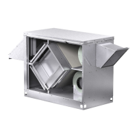
Vari-Green
®
Electronically
Commutated (EC) Motor
Features
Soft Start – All motors
feature soft-start technology
which eliminates inrush
current at start-up. The
motors will reliably start at
any speed setting.
Overload Protection – If the motor becomes
overloaded, it will automatically reduce its speed until it
is no longer overloaded. This means that the motor will
never operate in the “service factor” which is possible
with many AC motors.
Locked Rotor Protection – If the motor ever
encounters a locked-rotor scenario, the motor will
automatically shut itself down. It will try to restart up to
3 times and if after the 3rd time the motor will still not
rotate, the motor will not attempt to start again until
power is cycled.
Thermal Protection – The motors will have an internal
thermal protection which electronically regulates the
RPM limit until an acceptable temperature is met.
Operation and Wiring
These motors have the ability to accept a plug in
potentiometer for speed adjustment AND the ability to
accept a 0-10V signal for remote control.
Motor Potentiometer - Turn the dial with your fingers to
adjust. To increase the speed, rotate the dial clockwise.
To decrease the speed, rotate the dial counterclockwise.
Turning the dial full counterclockwise will turn the motor
off.
0-10 VDC Signal - From 0-1.9V, the motor will be off
and will operate within the 2-10V range. This motor
does not require 24V power for operation.
 Loading...