Unit
Size
6 - - - 3/8 -
7 - - - 3/8 -
9 - - - 1/2 1/2
10 3/8 1/4 5/32 1/2 1/2
12 3/8 - 5/32 - 1/2
13 7/16 1/4 5/32 - 1/2
15 1/2 1/4 5/32 - 1/2
16 1/2 1/4 5/32 - -
18 5/8 3/8 5/32 - 1/2
20 5/8 3/8 5/32 - 5/8
22 11/16 - 5/32 - 5/8
24 3/4 3/8 5/32 - -
25 - - - - 3/4
27 7/8 - 3/16 - 3/4
30 15/16 1/2 3/16 - 3/4
33 1-1/16 - 3/16 - -
36 1-3/16 1/2 3/16 - -
4
PRE-STARTING CHECKS
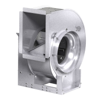
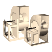
Wheels must rotate freely and not rub on the inlet
venturi. Model SWB wheels overlap the inlet venturi
as shown in Figure 2. Refer to the SWB fan wheel
overlap and radial gap chart for proper dimensions.
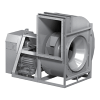
Models SFD and SFB wheels do not overlap the
venturi, but have a gap between the inlet venturi and
the wheel (Fig. 3). Wheel position is preset at the
factory and the unit is test run. Wheel movement
may occur during shipment or installation and wheel
alignment may be necessary.
On belt drive units, centering can be accomplished
by (1) loosening the inlet cone bolts to move the
inlet cone or by (2) loosening the bearings in order
to move the shaft. Wheel and inlet cone overlap can
be adjusted by loosening the wheel hub set screw
and moving the wheel to the desired position.
Tighten all fasteners and set screws securely and
realign drive pulleys after adjustment. Check pulleys
and belts for proper alignment to avoid unnecessary
belt wear, noise, vibration and power loss. Motor
and drive shafts must be parallel and pulleys in line
(Fig. 4)
The adjustable motor pulley is set at the factory for
the fan RPM specified by the customer. Fan RPM
can be increased by closing or decreased by
opening the adjustable motor pulley. Multi-groove
variable pitch pulleys must be adjusted an equal
number of turns open or closed. Any increase in fan
speed represents a substantial increase in load on
the motor.
To avoid motor overheating and possible burnout,
motor load amperes should always be checked and
compared to nameplate rating when fan speed is
increased.
Rotation direction of the wheel is critical and
incorrect rotation will result in reduced air
performance, increased motor loading and possible
motor burnout.
MODEL SWB
Fig. 2
Wrong Wrong Right
Fig. 4
APPROXIMATE WHEEL CLEARANCE DIMENSIONS
Overlap (inches)
Series
100
Series
200
Radial Gap
(inches)
SWB
SFD
GAP
(in.)
SFB
GAP
(in.)
MODEL SFD OR SFB
Fig. 3
 Loading...