Greenlee Textron Inc. / Subsidiary of Textron Inc.
10
4455 Boeing Dr., Rockford, IL 61109-2988 815/397-7070
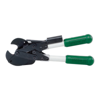
764 Ratchet Cable Cutter
Note: Use Loctite
®
#262 on all screws and tighten all
5/16" diameter screws to 190/170 inch pounds.
Use Loctite
®
#416 adhesive (cyanoacrylate) to
attach boot and release pin bumpers (10).
Lubricate moving parts with Molykote
®
grease
(see Figure 1).
Assembly (cont’d)
1. Assemble handle assembly (39) to bottom of
housing plate (13) using two screws (11).
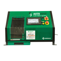
2. Assemble stop pin (20). Place a spare 3/8" diameter
by 1-1/2" screw through the master gear hole in
bottom housing plate (13) and place assembly on
bench with screws up (see Figure 2).
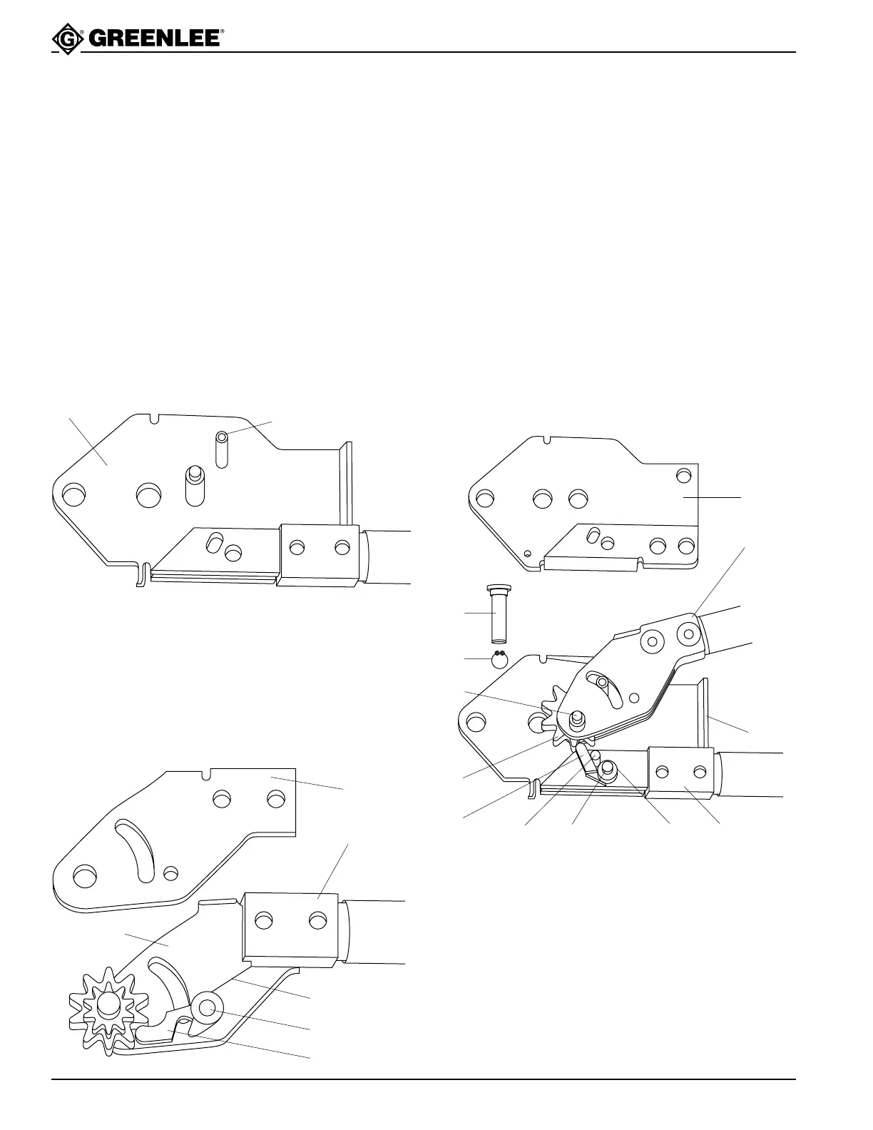
3. Lubricate pawl shaft (19) and assemble pawl shaft,
pawl (15) with pin (37) projecting from pawl surface,
spring (12), bottom handle plate (14) and top handle
plate (22) to handle assembly using two screws
(11). The long leg of the spring goes against the
bottom handle adapter (28) and the short leg goes
under the pawl (see Figure 3).
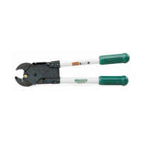
4. Insert master gear (16) between top and bottom
handle plates against drive pawl (15) and assemble
over “spare” screw in bottom housing plate
(see Figure 4).
5. Place holding pawl (15) with release pin (27) and
spring (17) over hole in bottom housing plate and
insert lubricated pawl shaft (19). The pawl will
engage the master gear. The long leg of the spring
goes against the handle adapter (28) where it
touches the bottom housing plate and the short leg
goes under the pawl (see Figure 4).
6. Thread housing cover (35) between handle plates
above the master gear—between spring (17) and
handle adapter (28) (see Figure 4).
Maintenance (cont’d)
14
22
28
19
15
12
Figure 3
13
20
Figure 2
26
9
26
16
15
27 19 17 28
13
28
23
Figure 4