1514
W
R
G
C
Y
W
R G
Y
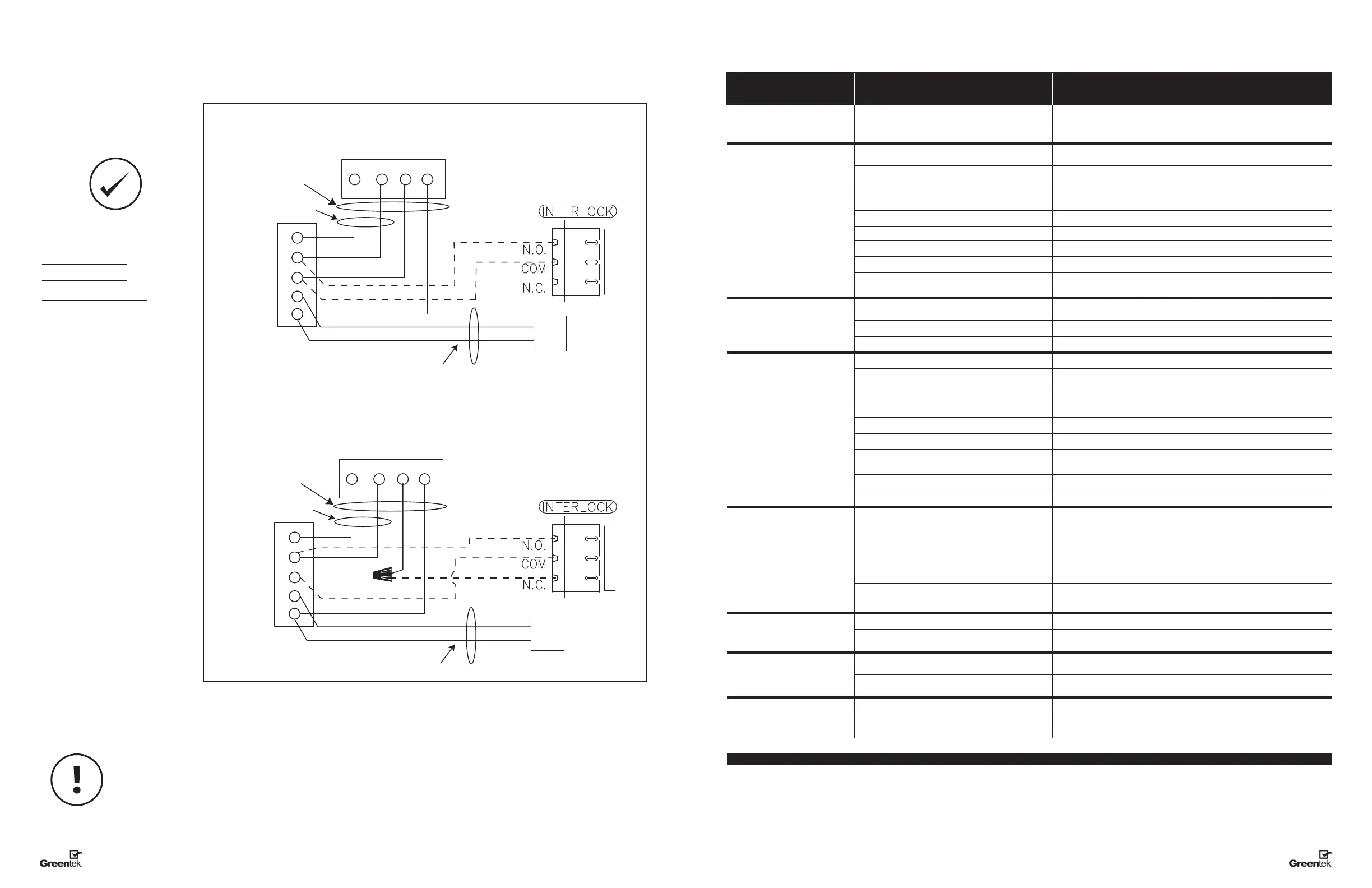
Standard Furnace Interlock Wiring
THERMOSTAT
TERMINALS
FURNACE
24-VOLT
TERMINAL BLOCK
FOUR
WIRE
TWO WIRE
heating only
TWO
WIRE
COOLING SYSTEM
W
R
G
C
Y
W
R G
Y
Alternate Furnace Interlock Wiring
THERMOSTAT
TERMINALS
FURNACE
24-VOLT
TERMINAL BLOCK
FOUR
WIRE
TWO WIRE
heating only
TWO
WIRE
COOLING SYSTEM
WIRE JOINT
WIRING DIAGRAM (CONT'D)
WIRING DIAGRAM TO
FURNACE
FOR A FURNACE
CONNECTION TO
A COOLING SYSTEM:
On some newer furnaces and older
thermostats, energizing the R and
G terminal at the furnace has the
effect of energizing the Y at the
thermostat and thereby turning on
the cooling system. If you identify this
type of thermostat, you must use the
“Alternate Furnace Interlock Wiring.”
Standard Accessory Control Contact
Alternative Accessory Control Contact
As per building codes and installation requirements for combustion appliances:
Air return ducts, or openings for air return, should not be placed in enclosed spaces containing combustion
appliances that are subject to spillage.
TROUBLESHOOTING
Problem Causes Solutions
Air is too dry Dehumidistat control is set too low Increase the desired level of humidity. Change ventilation mode from
continuous mode to standby.
HRV out of balance Have contractor balance HRV airows
Air is too humid Dehumidistat control is set too high Reduce the desired level of humidity. Combine this with the use of continuous
exchange mode.
Sudden change in temperature Wait until outside temperature stabilizes (winter). Heating will also improve
the situation.
Storing too much wood for heating Store a majority of your wood outside. Even dried, a cord of wood contains
more than 20 gallons of water.
Dryer vent exhaust is inside home Make sure the dryer vent is exhausting outside.
Poor air circulation near windows Open curtains or blinds.
HRV out of balance Have contractor balance HRV airows
Well sealed basement door is closed Open the door or install a grill on the door.
Failed damper system may be stuck in recirculation
mode
Check defrost damper. If damper is always blocking incoming fresh air, have
contractor verify damper system.
Persistent condensation
on window
Improper adjustment of dehumidistat control Reduce the desired level of humidity. Combine this step with use of continuous
exchange mode.
HRV out of balance Have contractor balance HRV
Poor air circulation near windows Open curtains or blinds.
Poor Air Flows 1/4" (6 mm) mesh on the outside hoods is plugged Clean exterior hoods or vents
Filters plugged Remove and clean lter
Core obstructed Remove and clean core
Indoor grilles closed or blocked Check and open grilles
Inadequate power supply at site Have electrician check supply voltage
Ductwork is restricting airow Check duct installation
Improper speed control setting Increase the speed of the HRV (i.e. change unit control from REDUCED to NORMAL
speed)
HRV airow improperly balanced Have contractor balance HRV airows
Ducting has fallen down or been disconnected from HRV Have contractor reconnect ducting
Supply air feels cold Poor location of supply grilles, the airow may irritate
the occupant
Locate the grilles high on the walls or under the baseboards, install ceiling
mounted diffuser or grilles so as not to directly spill the supply air on the
occupant (eg. Over a sofa)
Turn down the HRV supply speed. A small duct heater (1 kw) could be used to
temper the supply air
Placement of furniture or closed doors is restricting the movement of air in
the home
Outdoor temperature extremely cold If supply air is ducted into furnace return, the furnace fan may need to run
continuously to distribute ventilation air comfortably
HRV and/or Ducts frosting up HRV air ows are improperly balanced Have HVAC contractor balance the HRV airows
Malfunction of the HRV defrost system Note: minimal frost build-up is expected on the core before unit initiates
defrost cycle functions
Condensation or Ice Build Up in
Insulated Duct to the Outside
Incomplete vapor barrier around insulated duct Tape and seal all joints
A hole or tear in outer duct covering Tape any holes or tears made in the outer duct covering
Ensure that the vapor barrier is completely sealed.
LED is ashing Everything is in good operations
LED is not ashing No Power is being transmitted to the Control Board Make sure unit is plugged.
Transformer may need replacing.
Note: It is best to get the unit checked by a certied HVAC Contractor/Technician.
 Loading...