11
INSTALLATION CONTINUED
INSTALLATION LR-DRIVE
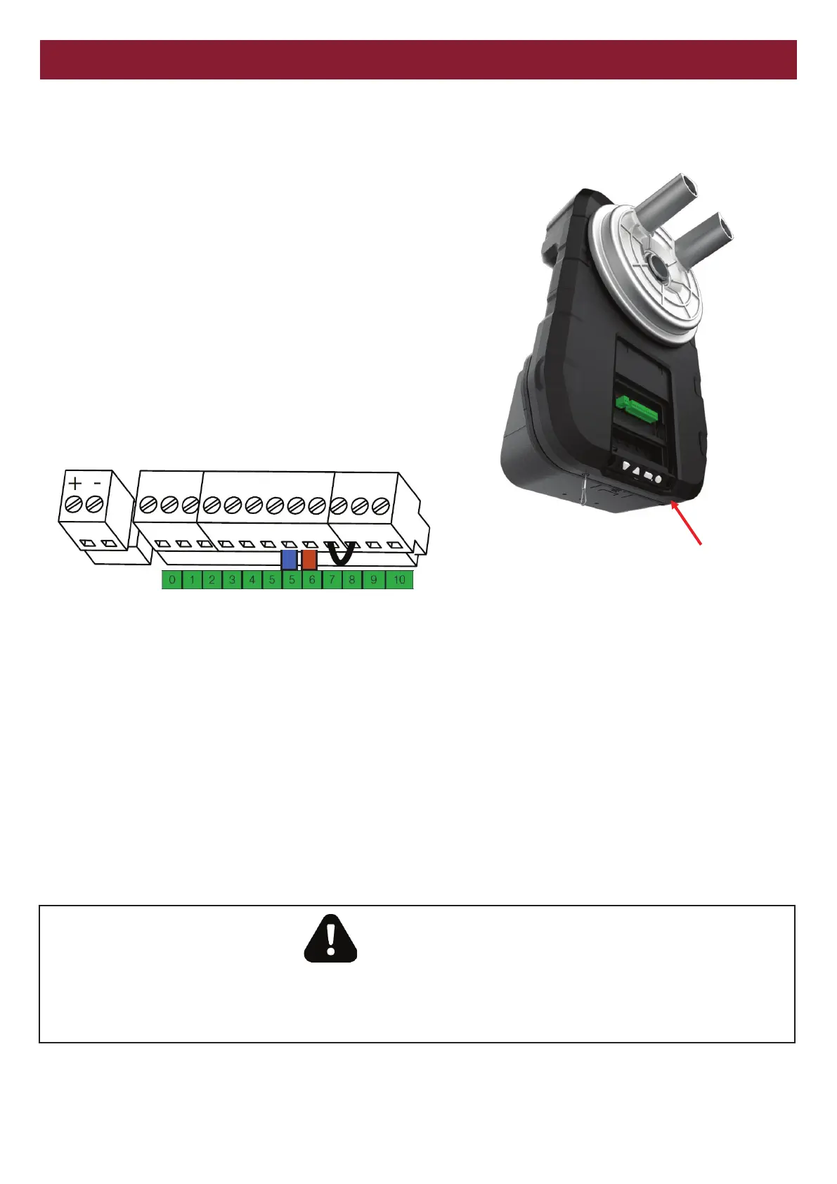
Cable entry
Run the photoelectric sensor cable via 20mm conduit into the 20mm
conduit entry located on the lower edge on the right hand side.
The cable will be internally routed to the terminal block.
Connection
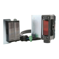
The photoelecric sensor is supplied prewired to a quick connect plug.
Using a small flat blade screwdriver, loosen the screws on the quick
connect plug, and remove the cables from the plug. The plug is not
needed.
As this product is polarity sensitive, ensure the Brown wire is
terminated into terminal number 6, and the blue wire is terminated into
terminal number 5
TO REMOVE AND ERASE MONITORED ENTRAPMENT
PROTECTION DEVICES
Remove the BBU connector and power down the operator. Power the
operator up for three seconds.
Remove power for three seconds.
Repeat three times, leaving power on the third time
Cable entry
Brown Blue
WARNING
Only one set of GPS15’s can be installed.
If two sets of safety beams are required, then install GPS772’s or 774ANZ’s