7
INSTALLATION CONTINUED
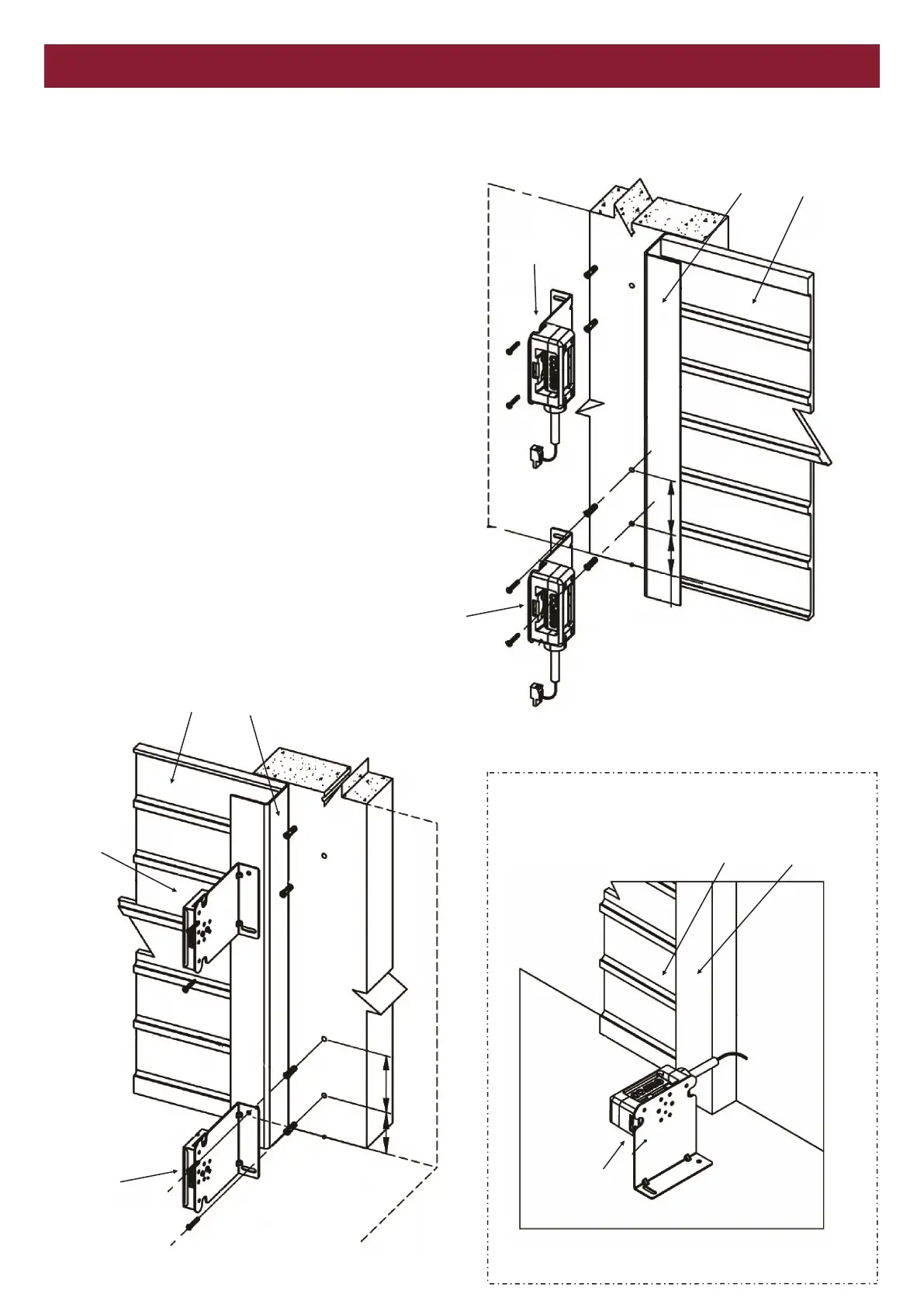
Figure 1 refers to the installation of the photoelectric sensor and
figure 2 refers to the installation of the reflector.
The photoelectric sensor (A) must be installed to detect an
obstacle of 100mm height. If additional detection height is
required, install a second photoelectric sensor (B) to meet the
functional requirements of the door.
Caution! Do not bend the bracket to align the photoelectric sensor
and the reflector.
Use 5.5mm or 6mm masonry drill bits and 6mm (green) wall plugs
and screws to install the bracket to the wall.
The photoelectric sensor and the reflector should be mounted at
the same height from the floor in order to achieve correct
alignment.
Install the secondary GPS15 (B) at a height above the primary
GPS15 (A) so that each GPS15 set works independently of each
other, and the sensors do not align with the other reflector.
Door Track Door
Door Track Door
Door Track Door
Photoelectric
sensor - B
Photoelectric
sensor - A
Reflector - B
Reflector - A
Photoelectric
sensor - A
60 mm 82 mm
60 mm 82 mm
Figure 2
Figure 1
Optional Floor Mounting
WALL MOUNTING