8
INSTALLATION CONTINUED
Be sure power to the operator is disconnected. Do not run control wiring in the same conduit with AC power.
The wire cable is intended to aid in the installation to either a junction box on the wall, or can be routed through the C10A mounted next
to the door allowing the wires to run in the same conduit as the control cable. The photoelectric sensor is also capable of receiving a 1/2”
thread conduit adapter.
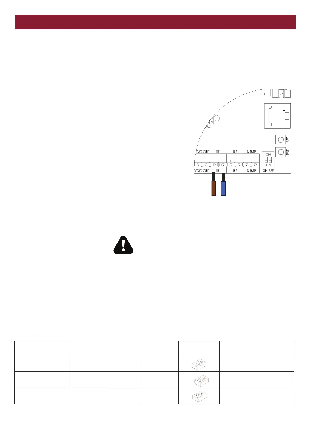
The photoelectric sensor is supplied prewired to a quick connect
socket which plugs directly into the IR1 position on the Grifco E-Drive
MCB.
If connecting a second photoelectric sensor, the quick connect socket
plugs into IR2.
As this product is polarity sensitive, ensure the Brown wire is
terminated on the Positive (+ve) terminal, and the Blue wire to the
Negative (-ve) terminal (as shown on the diagram to the right).
Note: Multiple PE beam sets can be installed at several heights for
special applications e.g. Fire Station, Ambulance Station etc.
A maximum of two sets of GPS photo beams can be installed using
the onboard power supply.
To erase the learnt entrapment devices from the MCB press and hold
the RST button for 10 seconds or until the green LED on
the MCB blinks rapidly.
WARNING
DO NOT CONNECT THE GPS15 to VDC OUT. The GPS15 must be connected to the IR1 or IR2 terminals only of the operator.
Connection to a voltage output or incorrect polarity will damage the unit and void warranty.
INSTALLATION E-DRIVE AND GLM
DIP SWITCH SETTINGS AND DOOR BEHAVIOUR
Setting door behaviour
To set the door behaviour modes, adjust the DIP switches in the corner of the MCB shown below. The different combinations suit
different behaviours and obstruction detection devices installed.
At default the MCB is set to latch open and inch close.
The door will open with a single press but only travel downwards while the down button is being held.
The door must only be set to latch DOWN if there is suitable Entrapment Protection device installed. Failure to do so can lead to serious
injury, death or damage to property.
-
+
Lower Right of the
MCB
Brown
Blue
Desired
Behaviour
PE Beam
installed
Dip Switch
1
Dip Switch
2
Latch Up Inch Down
(default)
N OFF ON Latch up / inch down
*Latch Up Latch
Down
Y ON ON *Latch up / latch down
**Inch Up
Inch Down
N OFF OFF **Inch up / inch down
Note: **Both dip switches must be OFF (inch up / inch down) for Coles & BI-LO electrically operated roller door installations
or when operator height is less than 2.5m from the ground without sufficient guarding of moving parts.