6
INSTALLATION
Identify the type and dimensions of your residential garage door or commercial rolling door. A check of the application is recommended to
ensure suitability of the Entrapment Protection device model to the door.
When properly connected and aligned, the photoelectric sensor will detect an obstruction in the path of its beam. If an obstruction breaks
the beam while the door is closing, the operator will stop and typically reverse to the full open position.
Check the following:
• The distance between the transmitter and reflector are within the specification of the Entrapment Protection device.
• Minimum distance 1.5m, maximum distance 15m.
• Photoelectric sensor can be mounted either left or right of the entrapment zone.
• The photoelectric sensor must be installed so that it faces the reflector across the entrapment zone.
• There is clearance either side of the door for the mounting brackets to be installed without any obstructions.
• The brackets must be installed securely to a solid surface such as the wall.
• Once installed, the Entrapment Protection device has a clear line between the photoelectric sensor and the reflector.
• Any environmental issue that may impede the operation of the GPS15. (e.g. excessive water, direct sunlight)
• Any reflective surface on vehicles or surroundings that may affect the operation of the GPS15.
• When installing GPS15 with bi-fold doors, position the photoelectric sensor and reflector so that the door does not break the beam
as it is operated.
• No part of the door (or door tracks, springs, hinges, rollers or other hardware) can obstruct the beam while the door is closing.
• When installing multiple GPS15's, ensure they are installed so that they function independently of each other, and the photoelectric
sensors do not align with the other reflector.
ENTRAPMENT PROTECTION
The Entrapment Protection System for your installation will be determined by the functional requirements of the door. To ensure the
installation meets these requirements refer to AS/NZS 60335-2-103.
When using the Grifco® Protector System as part of the Entrapment Protection System, ensure it is installed to detect a 100mm high
obstruction, ie; approximately 80mm from the floor.
Consideration should be given to the detection of vehicles or other similar equipment. To provide adequate Entrapment Protection,
additional Entrapment Protection System devices may be required to be installed in a sit specific position, for example, approx 600mm
from the ground.
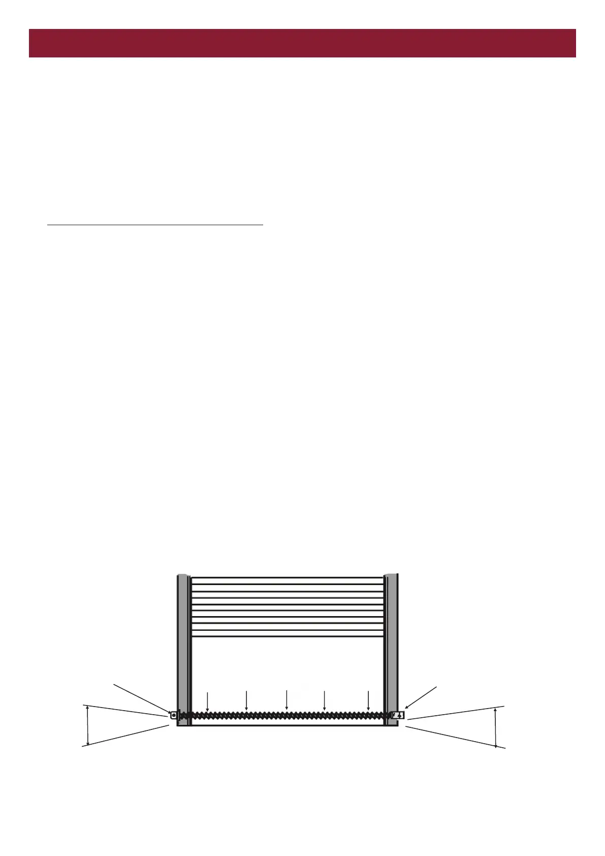
Make sure the brackets are aligned so that the photoelectric sensor and reflector will face each other across the entrapment zone as
illustrated.
Photoelectric Sensor
Mounted 80 mm above the
floor and away from the door
Reflector mounted 80 mm
above the floor and away
from the door
Invisible Light Beam Protection Area
Facing the door from the inside of the building.
(Installation procedures are the same for all door types)
80 mm
80 mm
PLANNING