-16-
Model G0708 (Mfd. Since 1/15)
Assembly
8. Using a Phillips screwdriver, remove the suc-
tion port baffle (Figure 9).
3.
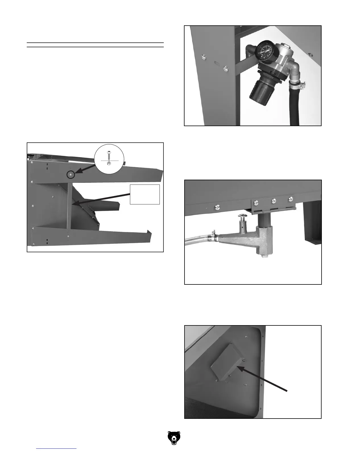
Attach the two side supports (Figure 6) to
the left and right set of legs with four cabinet
screws and flange nuts.
4.
With the help of an assistant, stand the blast
cabinet upon the legs.
5.
Remove the lamp box from inside of the cabi-
net, place the glass and the lamp box onto
the top of the cabinet, and fasten them to the
the cabinet with the six
1
⁄4-20 x
1
⁄2" cabinet
screws.
6.
Fasten the pressure gauge and regulator "L"
bracket (Figure 7) to the left front leg using
two cabinet screws and flange nuts.
To assemble the blast cabinet:
1.
With the help of an assistant, lay a sheet of
cardboard on the floor to protect the media
blasting cabinet, and place the cabinet on its
side or back.
2.
Using a #2 Phillips screwdriver, fasten all four
legs to the underside of the cabinet with (16)
1
⁄4-20 x
1
⁄2" cabinet screws and flange nuts
(Figure 6).
Figure 6. Leg installation.
Figure 7. Regulator assembly.
Figure 8. Hopper valve and chute door.
7.
Using three Phillips screws and flange nuts,
fasten the hopper valve and chute door to
the hopper, as shown in Figure 8. When
secured, latch the hopper door closed.
Figure 9. Suction port baffle.
Side
Support