3 OM-EE-20 & 40 (CE) INTERNATIONAL
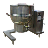
The unit will arrive in a heavy wooded crate and will be bolted or banded to a skid.
Immediately upon receipt, inspect the carton carefully for exterior damage.
Carefully cut any polyester straps around the carton and detach the sides of the
box from the skid. Pull the carton up off the unit.
Thoroughly inspect the unit for concealed damage. Report any shipping damage or
incorrect shipments to the delivery agent.
Write down the model number, serial number, and installation date, and retain this
information for future reference. Space for these entries is provided at the top of
the Service Log at the back of this manual. Keep this manual on file and available
for operators to use.
When installation is to begin, carefully cut any straps which hold the unit on the
skid. Lift the unit straight up off the skid. Examine packing materials to be sure
loose parts are not discarded with the materials.
Once the kettle is unpacked, the tangent draw-off valve is easily attached, as
shown above. The large nut which attaches the valve to the kettle should be hand
tightened only.
INSTALLATION
WARNING: INSTALLATION OF THE KETTLE MUST BE DONE BY A CERTIFIED
ELECTRICIAN OR AUTHORIZED REPRESENTATIVE QUALIFIED TO WORK
WITH ELECTRICITY. IMPROPER INSTALLATION CAN RESULT IN INJURY TO
PERSONNEL AN/OR DAMAGE TO EQUIPMENT.
DANGER: ELECTRICALLY GROUND THE UNIT AT THE TERMINAL PROVIDED. FAILURE
TO GROUND UNIT COULD RESULT IN ELECTROCUTION AND DEATH.
CAUTION: BEFORE ANY ELECTRICAL CONVERSION, VERIFY THAT THE BRANCH
CIRCUIT WIRING IS ADEQUATE TO HANDLE ANY INCREASE AMPERAGE
REQUIREMENTS. REFER TO THE ELECTRICAL SPECIFICATIONS LISTED
BELOW.
WARNING: DO NOT CONNECT ANY PIPING TO THE PRESSURE RELIEF VALVE. THE VALVE
MUST BE FREE TO VENT STEAM AS NEEDED. IMPROPER INSTALLATION
WILL VOID THE WARRANTY! THE ELBOW ATTACHED TO THE SAFETY VALVE
MUST POINT TO THE FLOOR. INSTALLATION WILL VOID THE WARRANTY!
THE ELBOW ATTACHED TO THE SAFETY VALVE MUST POINT TO THE FLOOR.
The kettle is provided with complete internal wiring and is ready for immediate
connection. Wiring diagrams are provided in this manual and on the inside of
the control housing service panel. Any mechanical or electrical changes must be
approved by the Food Service Engineering Department.
The completed unit has been operated at the factory to test all controls and heater
elements.
1. Set the kettle in place and level it by turning the bullet feet to adjust leg length.
Allow clearance around the unit for cleaning, maintenance and
service.
2. Confirm that the jacket water level is at the mid point of sight glass. If the level
is low, follow the instructions under “Jacket Filling and Water Treatment,” in
this manual.
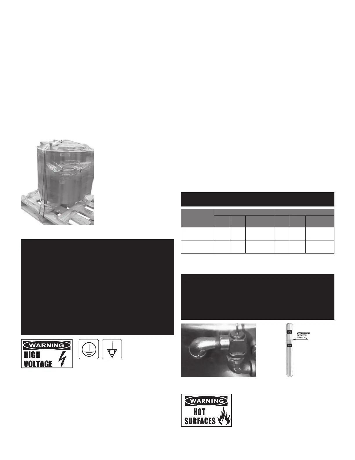
3. The open end of the elbow on the outlet of the pressure relief valve must face
downward. If it does not, turn it to the correct position.
4. Provide electrical power specified on the equipment electrical information
plate.
5. Bringing the electrical service through the entrance at the rear of the support
housing with 1-1/4” (35 mm) conduit, making a watertight connection with the
incoming lines.
6. Electrically protective earth ground the unit at the terminal provided (figure 1).
7. This unit is fitted with an equipotential terminal in accordance with national
regulations and CE directives. Locate this marking for equipotential terminal
connection (figure 2).
8. Check the following to confirm that your kettle is properly installed:
• Room for cleaning and servicing
• The kettle is level
• The correct amount of water is in the kettle jacket
• Pressure relief valve is pointed down
• Unit is connected with a waterproof supply of the proper voltage, phase
and amperage rating
ELECTRICAL SPECIFICATIONS
WARNING: USE COPPER WIRE RATED AT LEAST 75ºC (UNDER “ELECTRICAL
SPECIFICATIONS”).
Voltage/Phase
EE-20 EE-40
kW Amps Min. Wire Gauge kW Amps Min. Wire Gauge
230 V olt
Single-Phase
11 57
10 AWG
(6 mm
2
)
21 96
4 AWG
(24 mm
2
)
400 V olt
3-Phase
12 57
14 AWG
(2.5 mm
2
)
24 96
10 AWG
(6 mm
2
)
INITIAL START-UP
IMPORTANT: BE SURE ALL OPERATORS READ, UNDERSTAND AND FOLLOW THE OPERATING
INSTRUCTIONS, CAUTIONS, AND SAFETY INSTRUCTIONS CONTAINED IN THIS
MANUAL.
WARNING: AVOID ALL DIRECT CONTACT WITH HOT SURFACES. DIRECT SKIN CONTACT
COULD RESULT IN SEVERE BURNS. AVOID ALL DIRECT CONTACT WITH HOT
FOOD OR WATER IN THE KETTLE. DIRECT CONTACT COULD RESULT IN SEVERE
BURNS.
The open end of the pressure relief valve
elbow must face downward.
Correct water level.
Now that the kettle has been installed, you should test it to ensure that the unit is
operating correctly.
Figure 2Figure 1
 Loading...