7 OM-EE-20 & 40 (CE) INTERNATIONAL
SEQUENCE OF OPERATION
The following “action-reaction” outline is provided to help understand how the
kettle works.
When the operator starts up the kettle by turning the power switch “ON” and
heat knob from 0 to a desired setting, the control relay closes. This lights up the
heating indicator light and causes the contactors to close, allowing power to flow
to heating elements.
When the temperature of the steam jacket reaches the value corresponding to
the heat setting, the control relay opens. This turns off the heating indicator light
and causes the contactors to open, stopping the power to the heaters.
As soon as the controller senses that the kettle is cooling below the set point, the
control relay closes, the heating indicator light comes on, the contactors close,
and the heaters come on again. On-off cycling continues, keeping the kettle at
the set temperature.
This is why the heating indicator light cycles on and off during normal operation.
Every time the kettle is tilted, the tilt cut-off switch interrupts the power supply to
the heaters, so that the heating elements will not operate while not submerged
in the jacket water.
If steam pressure greater than 30 psi (206 kPa, 2.06 bar) is generated in the
jacket, the safety valve will open and relieve the excess pressure.
If the jacket water level gets too low before the heating elements overheat, the high-
limit control will open and shut off power to the elements until the kettle cools.
Setting the power switch dial to 0 shuts down all control and heating circuits.
The kettle has the following safety features:
1. Low water cutoff relay that will remove power from control and contactors
until the jacket water level is corrected.
2. High limit pressure switch, set to open at about 24 psi (165 kPa, 1.65 bar)
and to shut down the heat until jacket pressure is decreased.
3. Pressure relief valve, which will release steam if jacket pressure exceeds 30 psi
(206 kPa, 2.06 bar)
4. Tilt switch, which shuts off all heat when the kettle is tilted.
REPLACEMENT PARTS
To order parts, contact your Authorized Service Agent. Supply the model
designation, serial number, part description, part number, quantity, and when
applicable, voltage and phase.
CONTACT US
If you have questions pertaining to the content in this manual, contact Unified
Brands at 888-994-7636.
TROUBLESHOOTING
This unit is designed to operate smoothly and efficiently if properly maintained.
However, the following is a list of checks to make in the event of a problem.
Wiring diagrams are found at the end of this manual. When in doubt, turn unit
off and call for service at 888-994-7636. If an item on the check list is marked
with (X), it means that the work should be done by an Authorized Service Agent.
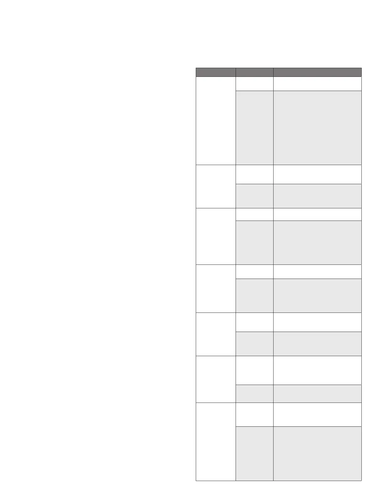
SYMPTOM WHO WHAT TO CHECK
Kettle will not
heat and heating
indicator will not
come on.
User a. Electric power supply to the unit.
b. Water level in jacket.
Authorized
Service Rep Only
c. Control circuit fuses in the control console.
X
REPLACE BLOWN FUSES ONLY WITH A
FUSE OF
THE SAME AMP RATING. A HIGHER RATED
FUSE
WILL NOT PROTECT THE UNIT OR THE
BUILDING.
d. For loose or broken wires. X
e. Operation of variable thermostat. X
f. Low water cutout switch. X
g. Water probe. X
h. That high limit pressure switch is closed.
X
Kettle will not
heat but heating
indicator comes
on.
User a. For air in the jacket. See “Jacket
Vacuum” in the “Maintenance” section of
this manual.
Authorized
Service Rep Only
b. Contactor. X
c. Heater elements with ohmmeter for
ground short or open element. If element
is defective, call Groen. X
Kettle continues
heating after
it reaches
the desired
temperature.
User a. Thermostat dial setting.
Authorized
Service Rep Only
b. Thermostat circuit for short. X
c. Thermostat calibration. X
d. Thermostat operation. The thermostat
should click when the dial is rotated to
settings above and below the temperature
of the kettle. X
e. Contactor, to determine whether it is
energized or stuck. X
Kettle stops
heating before
it reaches
the desired
temperature.
User a. Thermostat dial setting.
b. Jacket water level.
Authorized
Service Rep Only
c. Thermostat calibration. X
d. Thermostat operation. The thermostat
should click when the dial is rotated
above and below the setting for the
temperature of the kettle. X
e. Pressure limit the switch. X
Kettle heats
slowly.
User a. For air in the jacket. See “Jacket
Vacuum” in the “Maintenance” section of
this manual.
Authorized
Service Rep Only
b. Heater elements with ohmmeter for
ground short or open element. If an
element is defective, call Groen. X
c. Voltage of main power source. X
Safety valve leaks
a small amount of
steam when the
kettle is operating.
User a. For contamination that prevents seating of
valve. With full pressure in the jacket, pull
the lever all the way briefly to blow the
valve clean, then let the lever snap back
to seat the valve.
Authorized
Service Rep Only
b. Safety valve for defects. Replace any
defective valve with an identical valve. X
Safety valve pops. User a. For air in the jacket. See “Jacket Vacuum”
in the Maintenance section of this manual.
b. Whether kettle was being heated empty
when valve popped.
Authorized
Service Rep Only
c. Pressure limit switch. X
d. Thermostat operation. Thermostat should
click when the dial is rotated above and
below the setting for the temperature of
the kettle. X
e. Safety valve. If the valve pops at
pressures below 196 kPa (28 psi), replace
it. X
f. Contactor, to determine whether it is de-
energized. X
 Loading...