OM-TDB/7
8
Installation
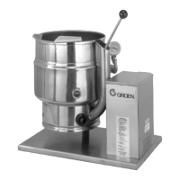
The Groen Kettle is provided with
complete internal wiring. It is ready for
immediate connection. A wiring diagram
is provided in this manual and on the
inside of the control housing service
panel. Any mechanical or electrical changes must be
approved in by Groen’s Food Service Engineering
Department.
WARNING
INSTALLATION OF THE KETTLE MUST BE
DONE BY PERSONNEL QUALIFIED TO
WORK WITH ELECTRICITY. IMPROPER
INSTALLATION CAN RESULT IN INJURY
TO PERSONNEL AND/OR DAMAGE TO
EQUIPMENT.
The completed unit has been operated at the factory
to test all controls and heater elements.
1. Set the kettle in place and level it. The base
should be securely fastened to a table or work
surface. Four 3/8”-16 N.C. threaded couplings
are provided in the base of unit. Installation
under a ventilation hood is recommended.
2. Provide electrical power as specified on the
electrical information plate attached to the
equipment. Observe local codes and/or The
National Electrical Code in accordance with
ANSI/NFPA 70 - (current edition).
3.
The equipment is shipped ready for three phase
operation. Refer to the wiring diagram for single
phase operation.
4.
Bringing the electrical service through the
entrance at the rear of the support housing,
making a watertight connection with the
incoming lines. (A BX connection is not
recommended.)
DANGER
ELECTRICALLY GROUND THE UNIT AT
THE TERMINAL PROVIDED. FAILURE TO
GROUND UNIT COULD RESULT IN
ELECTROCUTION AND DEATH.
5.
Confirm that the jacket water level is above
mid point of sight glass (new models) or
between the marks on the gauge glass (old
models). If the level is low, follow the
instructions under “Jacket Filling and Water
Treatment” in the “Maintenance” section of
the manual.
6.
The open end of the elbow on the outlet of
the safety valve must be directed downward
on old models. If it is not, turn the elbow to
the correct position. On new models the
safety valve points down.
7.
Any mechanical or electrical change must be
approved by the Groen Food Service
Engineering Department.
TDB/7 ELECTRICAL SPECIFICATIONS
20 QUARTS 40 QUARTS
VOLTAGE PHASE KW AMPS KW AMPS
208 1 6.3 31 10.8 52
208 3 6.3 18 10.8 30
240 1 8.4 35 14.4 60
240 3 8.4 20 14.4 35
480 1 6.3 13 12.0 25
480 3 6.3 8 12.0 15
400 3 7.8 11.2 13.2 19
TDB/7 SUPPLY WIRE REQUIREMENTS
Copper only, THHN (90°C)
20 QUARTS 40 QUARTS
VOLTAGE PHASE AWG mm AWG mm
208 1
3
8
12
—
—
6
8
—
—
240 1
3
8
10
3.0
—
4
8
3.5
—
480 1
3
14
14
—
—
10
12
400 3 — 1.8 —
2.5
 Loading...