Functionalspecications
SCS_BA_EV-301_601_EN_12 groupscs.co.uk Date: 31.05.2023
info@groupscs.co.uk Issue: 1.2 / 06.2023
Page 10
4.3. Control electronics
The complete control of the EV-x01 is by a microcontroller.
The control functions consist of:
● the control of the I / U-charge
● the monitoring and switching of the power supply source
(mains-/emergency power supply operation)
● the inspection of the monitored functions (detection loops,
fuse, overload, etc.)
● the activation of the load output
● the activation of the volt-free contact
● the activation of the operational status indicator
(OK, ALARM and FAULT)
4.3.1. Mains/emergencypowerswitching
In case of power outage or under-voltage of the power supply
or error within the power supply, the EV-x01 will switch to
the emergency power supply. This is done with the help of
monitoring (monitor function). With this, the control electronics
can switch to emergency power operation at an early stage
and avoid an output voltage disruption.
4.3.2. Override Switch EV-HE077
The override switch EV-HE077 was especially designed for
this system and requires only 3 wires.
There are two buttons for OPEN(Boost) and CLOSE (Reset).
For visualization of the operation conditions there are three
LED‘s and an audible signal (buzzer). There is a mute
function for a certain time for the buzzer in case of failure.
After this time the buzzer will be active.
Visualization of the operation conditions:
● OK: green LED is on – system ready
● ALARM: red LED in on – buzzer is active
● FAULT: yellow LED is blinking – buzzer is active
4.3.3. Motor outputs on emergency power
All EV-x01 outputs are equipped with over load protection.
During emergency power operation all relays deenergize
after 3 minutes (maker opens again and breaker closes).
4.3.4. Signal contact on emergency power
During emergency power operation all relays deenergize
(maker opens again and breaker closes).
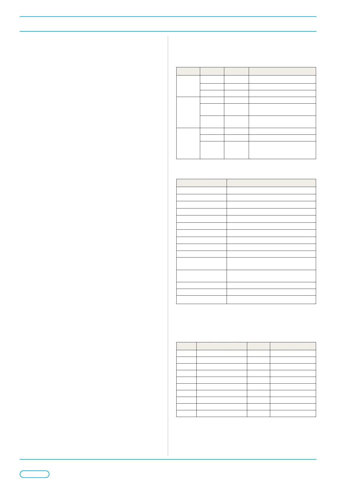
4.3.5. Operational status indicators
(OK, ALARM and FAULT)
Three onboard coloured LED’s indicate the status of the panel
and is repeated on the local EV-HE077 override switches.
LED State Buzzer Condition
OK
(Green)
O On Panel fault
On O Panel healthy
Flashing Muted Panel is in test mode
ALARM
(Red)
O O No alarms active
On On
In an alarm condition with vent
output open
Flashing On
In an alarm condition with vent
output closed
FAULT
(Amber)
O O No fault or warning conditions
On O In programming mode
Flashing On
A fault is active.
Morse code ashing identies
the fault condition*
The FAULT LED consist of a series of short (•) and long (—)
ashes with a long pause before the sequence is repeated.
Flashing Sequence Fault condition
• — — •
Primary supply mains failure
— — —
Motor output in overload
• •
Service due timer expired
• —
Power supply or battery failure
• • — •
Motor fuse fault
• — — — —
Line fault on motor 1
• • — — —
Line fault on motor 2
— • • —
Override switch input B1 in alarm
— • — —
FAS1 input B2 in alarm
— — • • FAS2 input B3 in alarm
— — • Gap open ventilation timer
programming mode
— • — • Automatic close ventilation timer
programming mode
• — — Master communication failure
— • Conguration or addressing error
• — • • Lockout mode
4.3.6. Addressing
The panel has a Databus interface and the panel address
can be set between the range of 1 – 255 by switch SW2 in a
binary format.
SW2 ON OFF Function
10 Standalone / SP-mode Network Operation mode
9 Not used Default No function
8 +128 0 Address Value 128
7 +64 0 Address Value 64
6 +32 0 Address Value 32
5 +16 0 Address Value 16
4 +8 0 Address Value 8
3 +4 0 Address Value 4
2 +2 0 Address Value 2
1 +1 0 Address Value 1
 Loading...