Commissioning Instructions
SCS_BA_EV-301_601_EN_12 groupscs.co.uk Date: 31.05.2023
info@groupscs.co.uk Issue: 1.2 / 06.2023
Page 22
ATTENTION
For maintenance purposes install an all-pole mains switch
(N, L1) before the panel.
INFORMATION
The use of shielded wires is recommended for the detec-
tion loops.The insulation resistance must display at least
20 MΩ/km. Manufacturer‘s technical information is to be
observed when installing the cabling.
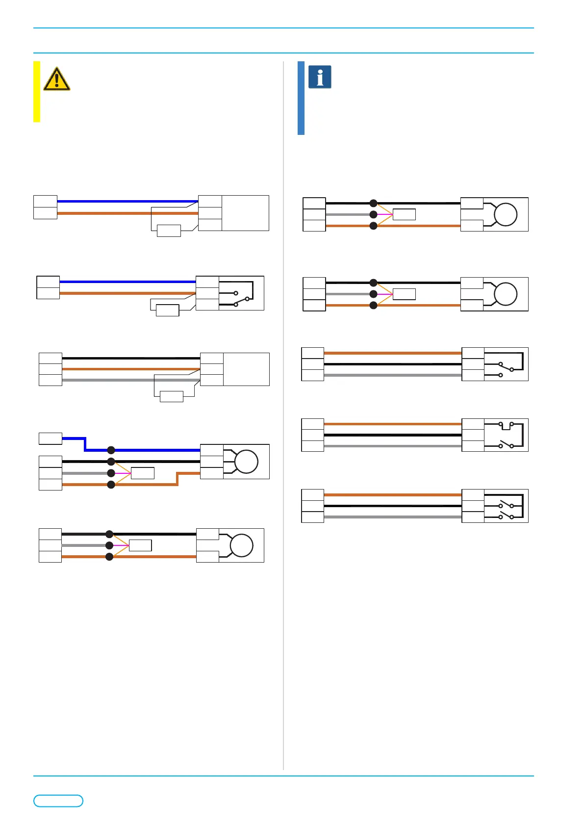
8.4.2. Wiring Details SP-Mode
Figure 7: Smoke Detectors (SP-mode)
-
B2 IN+
EV-SD
Smoke Detector
FAS1
COM-
OUT+
27KΩ
Figure 8: Fire Alarm Interface (SP-mode)
-
B3 NO
Fire Alarm Interface
FAS2
COM
NC
27KΩ
Figure 9: Override Switches (SP-mode)
S1
B1 B1
EV-HE077
Override Switch
Override
Switch
S1
--
27KΩ
Figure 10: Smoke Damper (SP-mode)
-
S
O
3
2
Shaft Damper
24VDC Belimo
Backup
1
M
G EOL
JB
Motor 1
Figure 11: Door Opener (SP-mode)
S
O 2
Door Opener
24VDC Rev Polarity
1
MG EOL
JB
Motor 2
Figure 12: AOV/WindowActutator(SP-mode)
S
O 2
AOV Window Actuator
24VDC Rev Polarity
1
MG EOL
JB
Motor 1
Figure 13: Head of Stair Vent (SP-mode)
S
O 2
Head of Stair Vent
Head of Shaft Vent
24VDC Rev Polarity
1
MG EOL
JB
Motor 1
Figure 14: Thermostat (SP-mode)
E
Z Y1
EV-ITH
Thermostat in SP mode
Inputs
L
A Y2
Figure 15: Wind/RainSensor(SP-mode)
ES
-
LZ
Inputs
5
EV-(W)RS
(Wind) Rain Sensor
1
2
Figure 16: Daily Ventilation Switch (SP-mode)
E
A
Open
EV-DVKS
Daily Ventilation Switch
Inputs
Com
Z Close