Commissioning Instructions
SCS_BA_EV-301_601_EN_12 groupscs.co.uk Date: 31.05.2023
info@groupscs.co.uk Issue: 1.2 / 06.2023
Page 18
8. Commissioning Instructions
DANGER
Disconnect both mains supply poles before connecting
any device to the interface panel.
ATTENTION
Never connect the battery during installation!
ATTENTION
If mains is not permanently guaranteed after installation,
there is a big risk of deep discharge of batteries! This will
lead to damage to the battery.
ATTENTION
The control board is sensitive to electrostatic discharge
causing damage to components. Do not remove or handle
the board, this may invalidate the warranty.
8.1. Commissioning EV-x01
The interface panel should be located outside the re zone
and positioned to be easily accessible for maintenance pur-
poses.
¾ Remove the lid by loosening the two screws on the
right-hand side of the panel and pivot from the locating
pin on the left. Disconnect the lid earth cable if required.
Do not allow the lid to hang on the earth cable.
¾ Position the interface panel and then mark the xing
holes (see gures 3, 4, 5
).
¾ Drill suitably sized xing holes and insert wall plugs for
5mm screws then x the box to the wall.
¾ Bring the required cables from the top or bottom into the
rear of the panel through the cable entry (see gures
3, 4, 5
).
¾ Secure the cables using the cable ties against the cable
entry teeth.
¾ Fasten the interface panel with four subsurface suitable
screws through the housing bottom (fastenings are not
included with delivery).
¾ Connect the cabling as per the relevant diagrams shown
in the Wiring Details section.
¾ EV-301-P: Bring the pressure tubing from the top in to
the rear of the panel through the cable entry shown in
gure 1 (2). Sleeve the tubing to insulate from the PCB
board then push in to the ttings (see gure 4
).
¾ Remove the terminating resistors of the SHEV-switch,
smoke detector and the FAS-contact from the clamps of
the central unit and connect to the triggering devices.
¾ Set the conguration DIP switches and jumpers
ATTENTION
Only batteries approved by the panel manufacturer should
be connected. Use of alternative batteries may void the
warranty
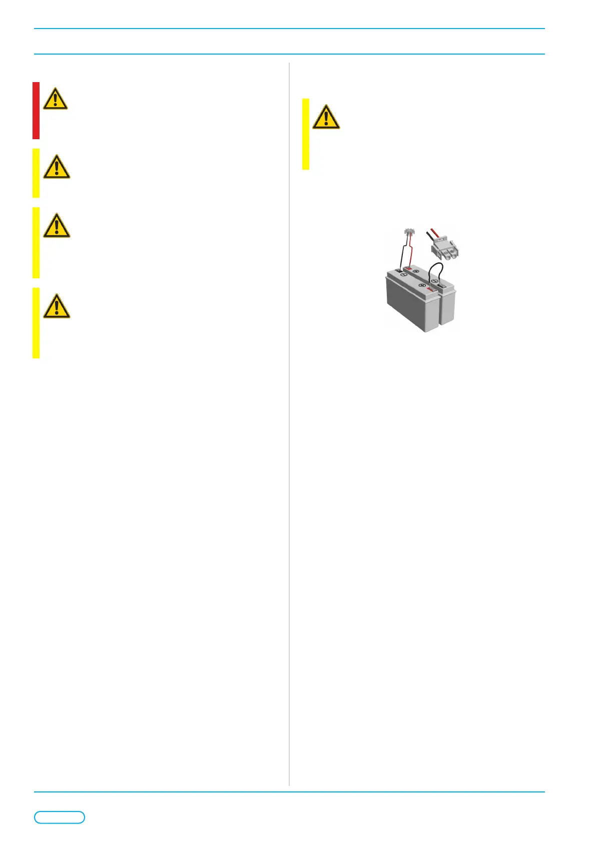
¾ Place batteries on the battery tray (see gures 3, 4, 5
)
and connect them to the board (battery connector X15)
with the supplied connection set.
Figure 1: Connection set
¾ Replace the lid by locating the pin on the left hand-side
and secure by tightening the two screws.
¾ Mark unit address and location on the front panel label
provided.
 Loading...