208Vac
3phase-
240Vac
3phase-
L1 L2 – PE L1 L2 – PE
NET MODEL:2
(Option)
NET MODEL:3
(Default)
wiring to terminal pin
NET MODEL
figure 5.6.3
WARNING
If several inverter are installed in a three-phase AC grid. it is
recommended to distribute the inverters between the phases in order
to reduce the power unbalances between the phases. Always refer to
the local standards.
si plusieurs inverter sont installés sur un réseau électrique à courant
alternatif à trois phases. Il est recommandé de distribuer les
onduleurs entre les phases pour réduire les déséquilibres de
puissance entre les phases. Toujours vous référer aux normes
locales.
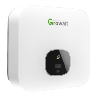
WARNING
Connection of the AC cable
Output connection terminal
Make sure the grid (AC utility) configuration types .If you grid standard is not the
factory default type, don’t worried, you just need to wire the local AC grid
according with the figure5.6.3, after wiring both DC input and AC output, you can
use the LCD to choose the NET model to make the inverter suit the local grid
type in the chapter 6.2 “Setting the LCD display”.
You must install a AC separate circuit-breaker or other load disconnection unit
between the inverter and utility, in order to ensure that the inverter can be safely
disconnected under load.
WARNING
The separate disconnection unit spec require as follow:
Voltage: the voltage much not less than the AC grid voltage which you
connection.
Current: the current much not less than 1.2 times of the inverter max
output current which defined in the inverter spec.
We suggest the AC separate unit spec as follow:
Grid type
@208Vac
@240Vac
GROWATT
12A/400Vac
12A/400Vac
1500-US
GROWATT
15A/400Vac
15A/400Vac
2000-US
GROWATT
20A/400Vac
20A/400Vac
3000-US
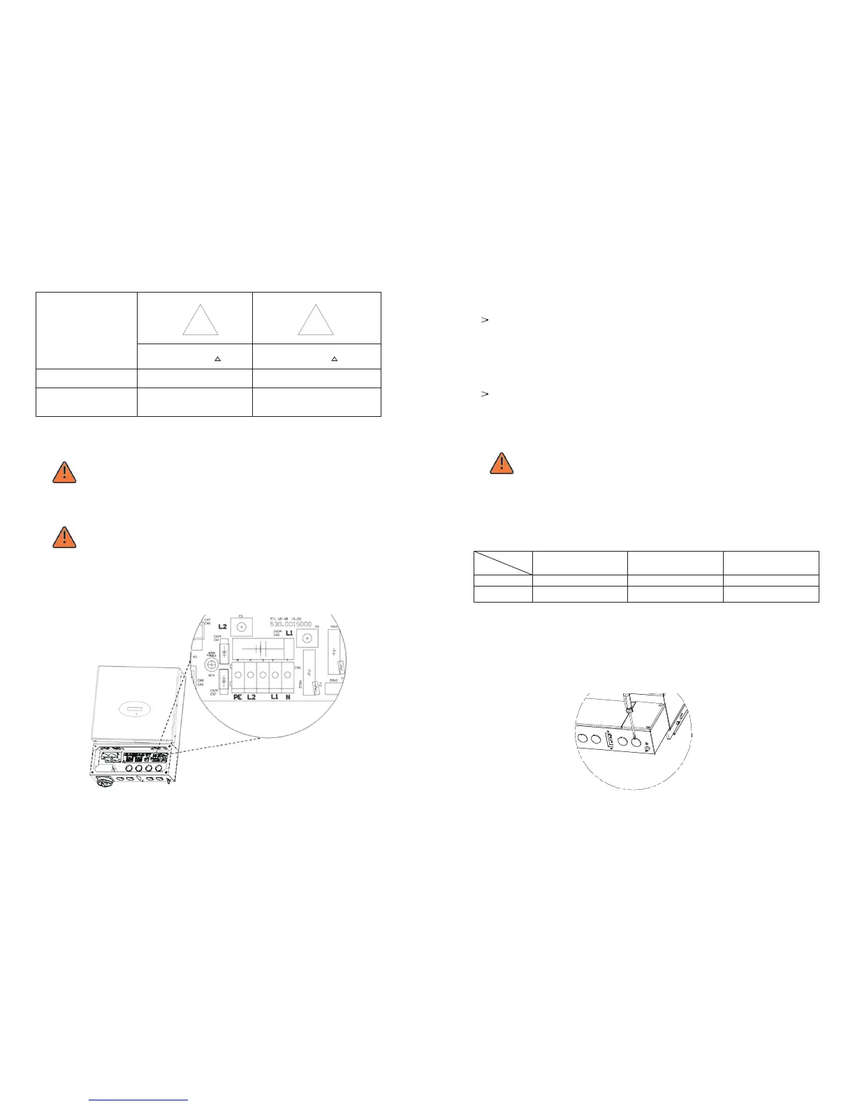
Wiring Step :
1.Open the AC separate unit between the inverter and utility and the DC switch on
the inverter.
2.Open the wire box cover and the knock-out hole.
Model