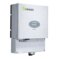
3.Installation rubber pipe into the knock-out hole and pull the pipe nut slightly, feed
the cables through the pipe into the wire box till the terminal.
4.The AC side terminal is clear, Connect cables into relevant terminals as the figure
5.6.3
Cable requirements
Area(mm²)
3.30~5.26
AWG No.
10~12
NOTICE
The cables length should not exceed 50 m, the resister of the cable will
consume inverter output power , finally reduce the inverter efficiency .
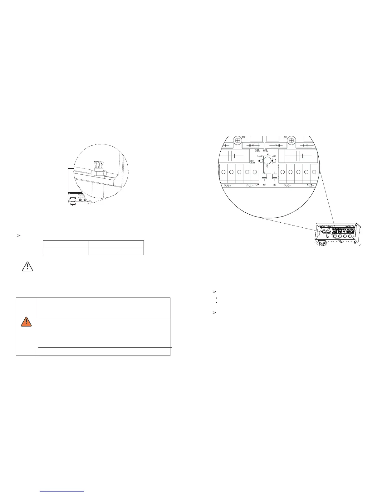
5.6.4 Connect to PV Panel (DC input)
Risk of electric shock and fire, use only with PV modules, and with a
maximum system voltage of 450Vdc@1500-US or
500Vdc@2000/3000-US..
DANGER
Electric shock hazard , the DC conductors of this photovoltaic system
are normally ungrounded but will become intermittently grounded
without indication when the inverter measures the PV array isolation.
Because of the transformer less design, the DC positive pole and DC
negative pole of PV arrays are not permitted to be grounded.
Do not disconnect the DC connectors under load!
Input connection terminal
Suggestions for the PV modules of the connected strings:
Same type
Same quantity of PV modules connected in series
Wiring inverter in parallel
The inverter can be connected in parallel in order to obtain more power, each
inverter shall connect to its own PV array, cannot connect a single PV array to
more than one inverter. That will cause the inverter to work abnormally, the worst
condition inverter will be damaged.
25 26