1 3 5 N L1 L1' L2 L2' L3 L3' N'
A
B
C
N
1 3 5 N L1 L1' L2 L2' L3 L3' N'
A
B
C
N
* * *
.
. .
B
A - + - +
RS485
Clock1 pulse
Clock2 pulse
G
1.LED status:the indicator LED is flashing or off.
Description:
(1)the red light is pulse output. the flash frequency of the red light
can show the power strength. the bigger power measured,the red
light will flash faster.
2.Fault description: the measurement is not inaccurate.
Suggestion: check the wiring of inlet and outlet of energy meter.
Namely, make sure that the wiring of A/B/C(three phase) of energy
meter is matched with the A/B/C phase of utility grid.
3.Fault description:the energy meter failed to communicate with
SPH.
Suggestion:
(1)check the“CT mode“ of SPH is “energy meter mode“.
(2)check the voltage between A+ and B- is within the range of
+(4.4~4.5)V
(3)check the RS485 communication cable is right. That is to say
the A+/B+ of energy meter is matched to A+/B- of SPH. Also,
make sure the wiring is fixed firmly.
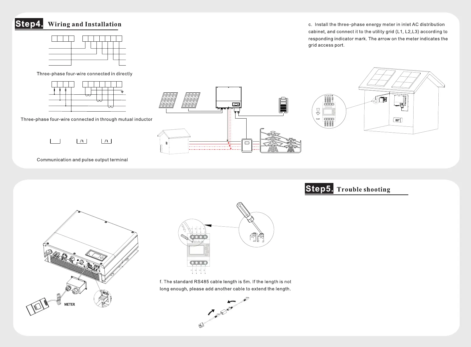
a.When SPH series products are used in three-phase power grid
system, please set the “CT mode” of SPH as “Meter Mode”.
More details, please refer to SPH user manual.
b. When connecting three-phase energy meter, SPH gets the
information of the sum of three-phase active power to process the
logical control by RS485 communication.
Note: We describe Growatt-SPH6000 and Growatt-SPH11000
TL3-HV as “SPH” as below.
d.Connect the end of the RS485 cable to SPH RJ45(Sensor)
port.
e. Connect the A+ of RS485 cable to Pin7 and B- of it to Pin8.
Meter
Load
RS-485
∑P≥0 , Charge
∑P≤0 , Discharge
L1
L2
L3
N

 Loading...