6.6 Installing the Comfort valves
Do not use Teflon tape, pipe joint
compound or pipe dope on the valve
threads.
Tighten the flex hose connections, plus
1/4 turn with a wrench. Overtightening
the flex hose connections can result in
valve damage, causing the valve to
leak and/or localized water damage.
When making pipe connections, be
sure to follow the pipe manufacturer’s
recommendations and all code
requirements for pipe material.
By plumbing convention, the hot water
is on the left side and the cold water on
the right side, when looking at the sink.
Your pipes may be different.
6.6.1 Valve location
For the greatest effect, the comfort valve must be
located at a faucet with the greatest pipe distance
from the hot-water heater. If a household consists
of more that one hot-water piping string, a comfort
valve must be mounted in each string.
6.6.2 Disconnecting the risers
1. Close both the hot- and cold-water angle stop
valves below the sink.
Cold-water
angle stop valve
Hot-water
angle stop valve
TM058973
2. Disconnect the risers.
TM058975
6.6.3
Installing the thermal bypass valve
Mounting hardware is not included.
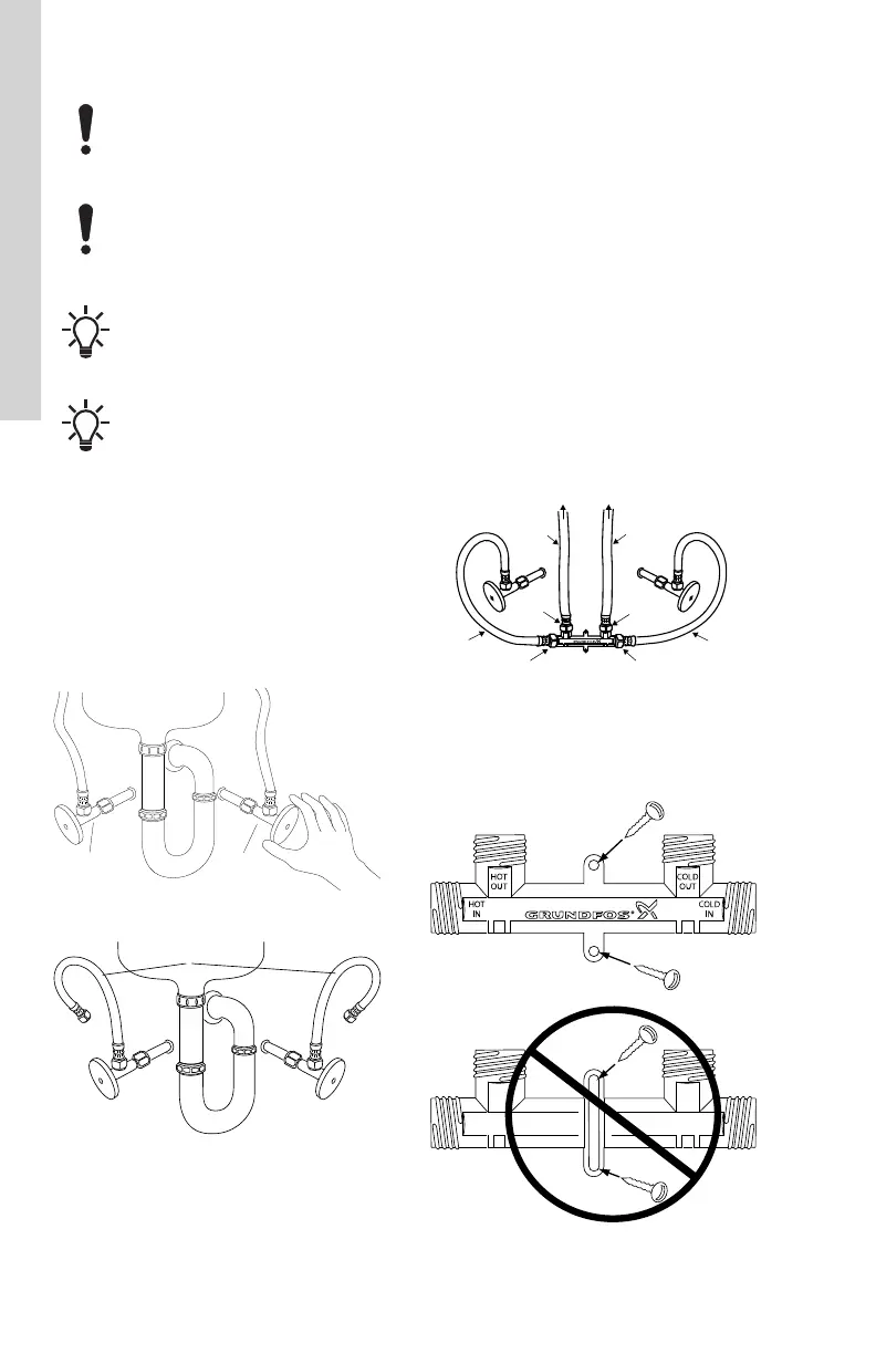
1. Connect the 1/2" x 1/2" flex hoses to the
ports on the thermal bypass valve marked
HOT OUT and COLD OUT.
2. Connect the 1/2" x 3/8" flex hoses to the
ports on the thermal bypass valve marked
HOT IN and COLD IN.
3. Connect the 1/2" hose fitting from the HOT
OUT port on the thermal bypass valve to the
left side of the faucet.
4. Connect the 1/2" hose fitting from the COLD
OUT port on the thermal bypass valve to the
right side of the faucet.
5. Connect the 3/8" hose fitting from the HOT IN
port on the thermal bypass valve to the left
angle stop valve.
6. Connect the 3/8" hose fitting from the COLD
IN port on the thermal bypass valve to the
right angle stop valve.
7. Open both hot- and cold-water angle stop
valves. Check for leaks.
1/2” x 1/2”
1/2” x 1/2”
1/2” x 3/8”
1/2” x 3/8”
To the faucet
HW
CW
HW OUT
HW IN CW IN
CW OUT
TM058976
Connection of thermal bypass valve, flex hoses,
and fittings
8. The thermal bypass valve may be mounted to
the wall with screws if desired.
TM058977
Correct installation of thermal bypass valve
(mounting hardware not included)
12
English (US)

 Loading...


