English (GB)
4
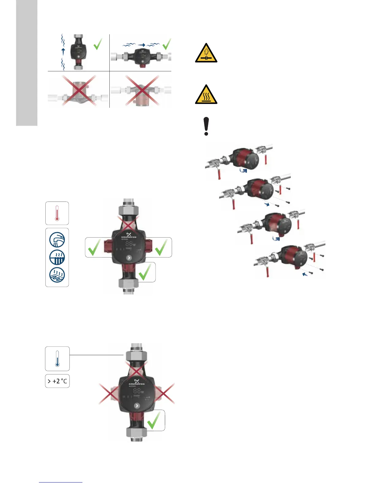
3.2 Positioning the pump
Fig. 2 Control box positions
Always install the pump with a horizontal motor shaft.
• Pump installed correctly in a vertical pipe. See fig. 2 (A).
• Pump installed correctly in a horizontal pipe. See fig. 2 (B).
• Do not install the pump with a vertical motor shaft. See fig. 2
(C and D).
3.3 Control box positions
3.3.1 Positioning of the control box in heating and domestic
hot-water systems
You can position the control box so that the plug is positioned at
3, 6 and 9 o'clock. See fig. 3.
Fig. 3 Control box positions, heating and domestic hot-water
systems
3.3.2 Positioning the control box in air-conditioning and
cold-water systems
Position the control box so that the plug is pointing downwards.
See fig. 4.
Fig. 4 Control box position, air-conditioning and cold-water
systems
3.3.3 Changing the control box position
Fig. 5 Changing the control box position
You can turn the control box in steps of 90 °.
1. Remove the four screws.
2. Turn the pump head to the desired position.
3. Insert and cross-tighten the screws.
TM06 9089 4317TM06 9090 4317TM06 9091 4317
WARNING
Pressurised system
Minor or moderate personal injury
- Before dismantling the pump, drain the system or
close the isolating valves on either side of the
pump. The pumped liquid may be scalding hot and
under high pressure.
CAUTION
Hot surface
Minor or moderate personal injury
- Position the pump so that persons cannot
accidentally come into contact with hot surfaces.
If you change the position of the control box, fill the
system with the liquid to be pumped or open the
isolating valves.
TM06 9092 4317