English (GB)
13
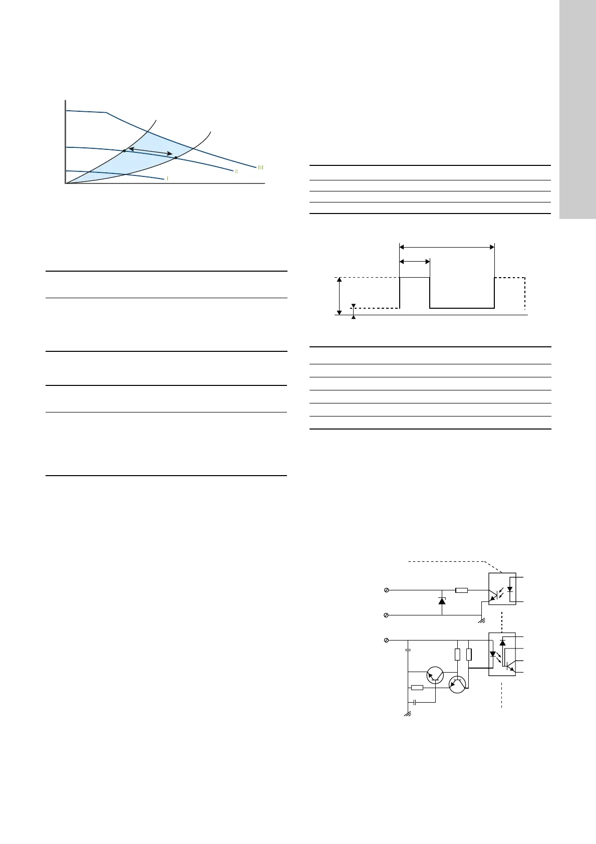
6.2.3 Constant curve or constant speed, I, II or III
At constant-curve or constant-speed operation, the pump runs at
a constant curve. The pump performance follows the selected
performance curve, I, II or III. See fig. 14 where II has been
selected.
Fig. 14 Constant-curve/-speed curve
The selection of the constant-curve or constant-speed setting
depends on the characteristics of the heating system in question.
6.2.4 Pump setting for one-pipe heating systems
Recommended and alternative pump settings:
6.2.5 Pump setting for domestic hot-water systems
Recommended and alternative pump settings:
6.2.6 Changing from recommended to alternative pump
setting
Heating systems are relatively slow systems that cannot be set to
the optimum operation within minutes or hours.
If the recommended pump setting does not give the desired
distribution of heat in the rooms of the house, change the pump
setting to the shown alternative.
6.3 Control signal
The pump can be controlled via a digital low-voltage pulse-width
modulation (PWM) signal.
The square-wave PWM signal is designed for a 100 to 4,000 Hz
frequency range. The PWM signal is used to select the speed
(speed command) and as feedback signal. The PWM frequency
on the feedback signal is fixed at 75 Hz in the pump.
For instructions on how to set the connection, see section
7.1 Setting the PWM input signal.
Duty cycle
d % = 100 x t/T
Example
Fig. 15 PWM signal
6.3.1 Interface
The pump's interface consists of an electronic part connecting the
external control signal to the pump. The interface translates the
external signal into a signal type that the microprocessor can
understand.
In addition, the interface ensures that the user cannot get into
contact with dangerous voltage if touching the signal wires when
power is connected to the pump.
Note: "Signal ref." is a signal reference with no connection to
protective earth.
Fig. 16 Schematic drawing, interface
TM06 8822 1217
System
type
Recommended control
mode
Alternative control
mode
One-pipe
heating
system
Constant curve or
constant speed, I, II or III.
See section
6.2.3 Constant curve or
constant speed, I, II or III.
No alternatives
System
type
Recommended control
mode
Alternative control
mode
Domestic
hot-water
system
Constant curve or
constant speed, I, II or
III. See section
6.2.3 Constant curve or
constant speed, I, II or
III.
No alternatives
Example Rating
T = 2 ms (500 Hz) U
iH
= 4-24 V
t = 0.6 ms U
iL
≤ 1 V
d % = 100 x 0.6 / 2 = 30 % I
iH
≤ 10 mA (depending on U
iH
)
TM04 9911 0211
Abbreviation Description
T Period of time [sec.]
d Duty cycle [t/T]
U
iH
High-level input voltage
U
iL
Low-level input voltage
I
iH
High-level input current
TM06 0787 0914
5
9
S
5
%&%
%&%
36
&1<)
N
N
PWM output
PWM input
Signal ref.
Galvanic isolation
Pump electronics

 Loading...