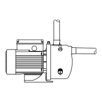
6. Fasten the support foot to the foundation.
TM081934
Make sure the support foot does not impose any tension
on the pump.
Related information
5.2.7 Positioning the inlet pipe
5.2.7 Positioning the inlet pipe
Make sure that the installation steps 1-3 are done before the inlet
pipe position is changed. See the section on assembling the motor
and the pump.
To change the position of the pipe, follow this procedure.
For BMS xl, follow the guide for BMS hp, and see the section on the
position of the inlet pipe.
1.
a. All pumps, excluding BMS hs 7-42: mark up the pump sleeve
and union nut, then loosen the screws.
TM059573
b. BMS hs 7-42: mark up the pump sleeve and union nut, then
loosen the screws.
TM077904
2. Turn the inlet pipe to the required position, and make sure the
union nut follows.
TM059343
3. Check that the markings are aligned.
TM059342
4.
a. Fit all screws again. All pumps excluding BMS hs 7-42:
tighten all screws to 33 Nm.
TM081933
b. BMS hs 7-42: tighten the M8 screw marked in the photo to 24
Nm and all other screws to 33 Nm.
TM077965
5. Fasten the support foot to the foundation.
TM081934
6. Check that the drain holes are positioned correctly. Note that
BMS hs 7-42 has no drain holes.
TM065336
Related information
5.2.6 Assembling the motor and the pump
5.3 BMS hp pump
5.3.3 Positioning the inlet pipe
5.2.8
Flushing the system
To avoid impurities in the pump, flush the pipes before you
connect the pump inlet and outlet pipes.
5.2.9 Pipe connection
Both the inlet and the outlet pipes are fitted with clamp liners for
Victaulic couplings and must be supported close to the end of the
pipe.
TM059230
Pipe support
8
English (GB)
 Loading...