English (GB)
13
10.Fit clamp (pos. 64c), washers (pos. 66) and nut (pos. 67).
See fig. 26.
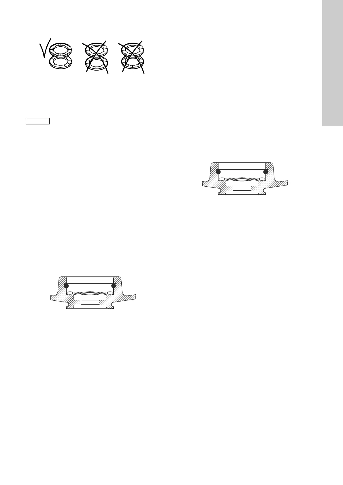
Fig. 26 Correct fitting of washers
11.Hold clamp (pos. 64c), and tighten nut (pos. 67).
See section 3. Tightening torques and lubricants.
12.Fit the chamber plate (pos. 4f).
13.Fit sleeve (pos. 16) and clamping flange (pos. 6a).
14.Fit and cross-tighten staybolts (pos. 26). See section
3. Tightening torques and lubricants.
5.6 MG 71 and MG 80 motors
5.6.1 Dismantling
1. Remove screws (pos. 152).
2. Remove fan cover (pos. 151).
3. Remove fan (pos. 156) and seal ring (pos. 159a).
4. Remove screws (pos. 181).
5. Remove motor flange (pos. 156b) and gasket (pos. 157a).
6. Remove diverting disc (pos. 79), O-ring (pos. 158a) and
bearing cover plate (pos. 155).
7. Pull shaft (pos. 51) out of stator housing (pos. 150).
8. Pull bearing (pos. 153) off shaft (pos. 51).
9. Remove O-ring (pos. 159) and spring (pos. 158).
10.Pull bearing (pos. 154) off shaft (pos. 51).
5.6.2 Assembly
1. Push bearing (pos. 154) onto shaft (pos. 51).
2. Fit spring (pos. 158) and O-ring (pos. 159). See fig. 27.
Fig. 27 Correct fitting of spring and O-ring
3. Push bearing (pos. 153) onto shaft (pos. 51).
4. Fit shaft (pos. 51) into stator housing (pos. 150).
5. Fit bearing cover plate (pos. 155), O-ring (pos. 158a) and
diverting disc (pos. 79). Lubricate the surface of the cover
plate (pos. 155) turning against the bearing. Lubricate the
O-ring (pos. 158a).
For correct lubricant, see section 3. Tightening torques and
lubricants.
6. Fit gasket (pos. 157a) and motor flange (pos. 156b).
7. Fit and cross-tighten screws (pos. 181). See section
3. Tightening torques and lubricants.
8. Fit and lubricate the seal ring (pos. 159a).
For correct lubricant, see section 3. Tightening torques and
lubricants.
9. Fit the fan (pos. 156).
10.Fit fan cover (pos. 151).
11.Fit and tighten screws (pos. 152). See section 3. Tightening
torques and lubricants.
5.7 MG 90, MG 100, MG 112 and MG 132 motors
5.7.1 Dismantling
1. Only cast iron pumps: Remove screws (pos. 2b).
2. Only cast iron pumps: Remove discharge part (pos. 2).
3. Remove screws (pos. 152).
4. Remove fan cover (pos. 151).
5. Remove fan (pos. 156) and seal ring (pos. 159a).
6. Remove staybolts (pos. 181).
7. Remove motor flange (pos. 156b), gasket (pos. 157a) and
bearing cover (pos. 156a).
8. Remove diverting disc (pos. 79), O-ring (pos. 158a) and
bearing cover plate (pos. 155).
9. Pull shaft (pos. 51) out of stator housing (pos. 150).
10.Pull bearing (pos. 153) off shaft (pos. 51).
11.Remove O-ring (pos. 159) and spring (pos. 158).
12.Pull bearing (pos. 154) off shaft (pos. 51).
5.7.2 Assembly
1. Push bearing (pos. 154) onto shaft (pos. 51).
2. Fit spring (pos. 158) and O-ring (pos. 159). See fig. 28.
Fig. 28 Correct fitting of spring and O-ring
3. Push bearing (pos. 153) onto shaft (pos. 51).
4. Fit shaft (pos. 51) into stator housing (pos. 150).
5. Fit bearing cover plate (pos. 155), O-ring (pos. 158a) and
diverting disc (pos. 79). Lubricate the surface of the cover
plate (pos. 155) turning against the bearing. Lubricate the
O-ring (pos. 158a).
For correct lubricant, see section 3. Tightening torques and
lubricants.
6. Fit bearing cover (pos. 156a), gasket (pos. 157a) and motor
flange (pos. 156b).
7. Fit and cross-tighten staybolts (pos. 181). See section
3. Tightening torques and lubricants.
8. Fit and lubricate the seal ring (pos. 159a). For correct
lubricant, see section 3. Tightening torques and lubricants.
9. Fit the fan (pos. 156).
10.Fit fan cover (pos. 151).
11.Fit and tighten screws (pos. 152). See section 3. Tightening
torques and lubricants.
12.Only cast iron pumps: Fit discharge part (pos. 2).
13.Only cast iron pumps: Fit and tighten screws (pos. 2b). See
section 3. Tightening torques and lubricants.
TM02 1057 0501
Do not forget to fit the chamber plate (pos. 4f), as
it is possible to assemble the pump without the
last chamber.
TM04 4441 1209
TM04 4441 1209
 Loading...