English (GB)
9
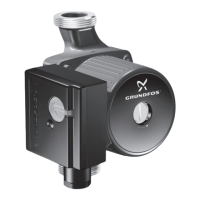
6. Fit spring (pos. 108) and driver (pos. 112). See fig. 7.
Fig. 7 Fitting the spring and driver
7. Fit impeller (pos. 49), spacing pipe (pos. 64), gasket
(pos. 139b) and chamber plate (pos. 4f).
8. Continue the assembly until chamber for bearing (pos. 4a).
9. Fit chamber for bearing (pos. 4a), short spacing pipe
(pos. 64a), gasket (pos. 139b) and bearing ring (pos. 47a).
See section 8. Order of assembly for chambers and impellers.
10.Fit impeller (pos. 49), clamp (pos. 64c), washers (pos. 66) and
nut (pos. 67). See fig. 8.
Fig. 8 Correct fitting of washers
11.Hold clamp (pos. 64c), and tighten nut (pos. 67).
See section 3. Tightening torques and lubricants.
12.Fit chamber (pos. 4e) and gasket (pos. 139b).
13.Fit inlet part (pos. 6).
14.Fit and cross-tighten staybolts (pos. 26).
See section 3. Tightening torques and lubricants.
5.3 CM 1, 3, 5, stainless steel
5.3.1 Dismantling
1. Remove staybolts (pos. 26).
2. Remove clamping flange (pos. 6a) and sleeve (pos. 16).
3. Remove chamber (pos. 4e).
4. Hold clamp (pos. 64c), and remove nut (pos. 67).
5. Remove lock washers (pos. 66) and clamp (pos. 64c).
6. Remove impeller (pos. 49).
7. Remove bearing ring (pos. 47a) and short spacing pipe
(pos. 64a).
8. Remove chamber for bearing (pos. 4a), impeller (pos. 49) and
spacing pipe (pos. 64).
9. Continue the dismantling until shaft seal (pos. 105).
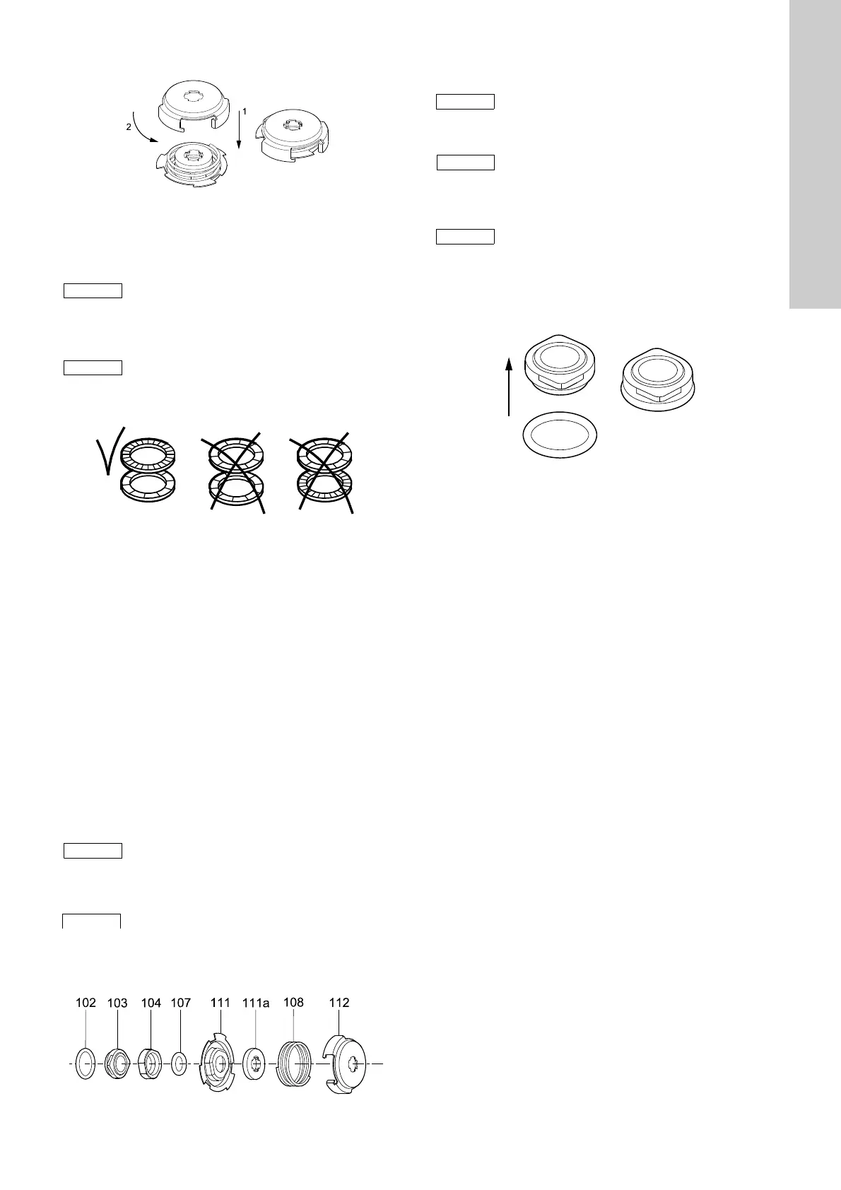
10.Remove shaft seal (pos. 105). See fig. 9.
Fig. 9 Exploded view of shaft seal
11.Remove O-ring (pos. 31) and cover plate (pos. 32).
5.3.2 Assembly
1. Fit cover plate (pos. 32) and O-ring (pos. 31). Lubricate the
O-ring. See section 3. Tightening torques and lubricants.
2. Fit O-ring (pos. 102) on the stationary shaft seal part.
See fig. 10. See section 3. Tightening torques and lubricants.
Fig. 10 Fitting the O-ring on the stationary shaft seal part
TM04 4326 1209
Step 8 applies only to pumps with eight stages.
Step 9 applies only to pumps with eight stages.
TM02 1057 0501
Step 7 applies only to pumps with eight or more
stages.
Step 8 applies only to pumps with eight or more
stages.
TM04 4327 1909
Dismantling of MG 71 and MG 80,
see section 5.6.1.
Dismantling of MG 90 and MG 100,
see section 5.7.1.
It is advisable always to replace wear rings
(pos. 45) and wear ring retainers (pos. 65).
See section 5.8.
Assembly of MG 71 and MG 80, see section 5.6.2.
Assembly of MG 90 and MG 100,
see section 5.7.2.
TM04 4322 1909
 Loading...