English (GB)
10
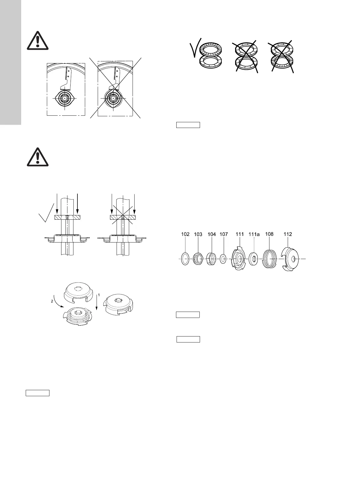
3. Press the stationary shaft seal part home. See fig. 11.
Fig. 11 Fitting the stationary shaft seal part (only SiC/SiC)
4. Fit the rotating shaft seal part (pos. 104) so that the seal face
touches the stationary part.
5. Fit O-ring (pos. 107) into the rotating shaft seal part
(pos. 104). See section 3. Tightening torques and lubricants.
6. Fit retainer (pos. 111) and stop ring (pos. 111a). See fig. 12.
Fig. 12 Fitting the stop ring
7. Fit spring (pos. 108) and driver (pos. 112). See fig. 13.
Fig. 13 Fitting the spring and driver
8. Fit impeller (pos. 49), chamber with holes (pos. 4d) and
spacing pipe (pos. 64).
9. Fit impeller (pos. 49), chamber (pos. 4) and spacing pipe
(pos. 64).
10.Fit impeller (pos. 49), chamber (pos. 4a), short spacing pipe
(pos. 64a) and bearing ring (pos. 47a). See section 8. Order of
assembly for chambers and impellers.
11.Fit impeller (pos. 49), clamp (pos. 64c), washers (pos. 66) and
nut (pos. 67). See fig. 14.
Fig. 14 Correct fitting of washers
12.Hold clamp (pos. 64c), and tighten nut (pos. 67).
See section 3. Tightening torques and lubricants.
13.Fit chamber (pos. 4e), sleeve (pos. 16) and clamping flange
(pos. 6a).
14.Fit and cross-tighten staybolts (pos. 26).
See section 3. Tightening torques and lubricants.
5.4 CM 10, 15, 25, cast iron
5.4.1 Dismantling
1. Remove staybolts (pos. 26).
2. Remove inlet part (pos. 6) and gasket (pos. 139b).
3. Hold clamp (pos. 64c), and remove nut (pos. 67).
4. Remove lock washers (pos. 66) and clamp (pos. 64c).
5. Remove impeller (pos. 49) and spacing pipe (pos. 64).
6. Remove chamber (pos. 4).
7. Continue the dismantling until shaft seal (pos. 105).
8. Remove shaft seal (pos. 105). See fig. 15.
Fig. 15 Exploded view of shaft seal
9. Loosen and remove screws (pos. 2b) and discharge part
(pos. 2).
Warning
Do not touch the seal face.
TM04 4435 1909
Warning
Do not touch the seal face.
TM04 4325 1909TM04 4326 1909
Step 10 applies only to pumps with eight or more
stages.
TM02 1057 0501
Do not forget to fit the last chamber (pos. 4e), as
it is possible to assemble the pump without the
last chamber.
TM04 4327 1209
Dismantling of MG 71 and MG 80,
see section 5.6.1.
Dismantling of MG 90, MG 100, MG 112 and
MG 132, see section 5.7.1.
It is advisable always to replace wear rings
(pos. 45) and wear ring retainers (pos. 65).
See section 5.8.
 Loading...


