6.2 Standard functional module, FM 200
6.2.1 Inputs and outputs
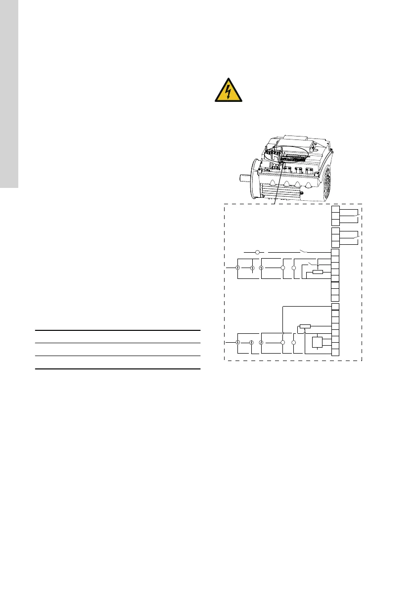
The module has these connections:
• two analog inputs
• two digital inputs or one digital input and one
open-collector output
• Grundfos Digital Sensor input and output
• two signal relay outputs
• GENIbus connection.
All inputs and outputs are internally separated from
the mains-conducting parts by reinforced insulation
and galvanically separated from other circuits. All
control terminals are supplied with protective extra-
low voltage (PELV), ensuring protection against
electric shock.
6.2.2 Signal relay 1
LIVE: You can connect supply voltages up to 250
VAC to the output.
PELV: The output is galvanically separated from other
circuits. Therefore, you can connect the supply
voltage or protective extra-low voltage to the output
as desired.
6.2.3 Signal relay 2
PELV: The output is galvanically separated from other
circuits. Therefore, you can connect the supply
voltage or protective extra-low voltage to the output
as desired.
6.2.4
Connection terminals for the mains supply
Phases Terminals
Single-phase N, PE, L
Three-phase L1, L2, L3, PE
6.2.5 Connection terminals for inputs and outputs
DANGER
Electric shock
‐ Death or serious personal injury
‐ Make sure that the wires to be connec-
ted to the connection groups below are
separated from each other by rein-
forced insulation in their entire lengths.
3
15
8
26
23
25
24
7
B
Y
6
5
2
4
10
A
AI2
GDS RX
GDS TX
GND
GENIbus A
GENIbus B
+5 V
+24 V
+24 V
GND
GENIbus Y
GND
+5 V
DI1
AI1
DI3/OC1
+24 V*
+
+
+24 V*/5 V*
+24 V*
+5 V*
NC
C2
NO
NC
C1
NO
+24 V*
+
+
+24 V*/5 V*
+24 V*
+24 V*
OC
DI
GND
TM053510
Connection terminals, FM 200
* If you use an external supply source, there must be
a connection to GND.
10
English (GB)

 Loading...


