English (GB)
5
7.2.1 Cable to condensate source or external
alarm
The Conlift has a safety overflow switch which can
be connected to the condensate source or to an
external alarm system. The switch is connected to an
alarm cable with free cable end.
Alarm systems with a control voltage of 250 VAC, 2.5
A, can be used.
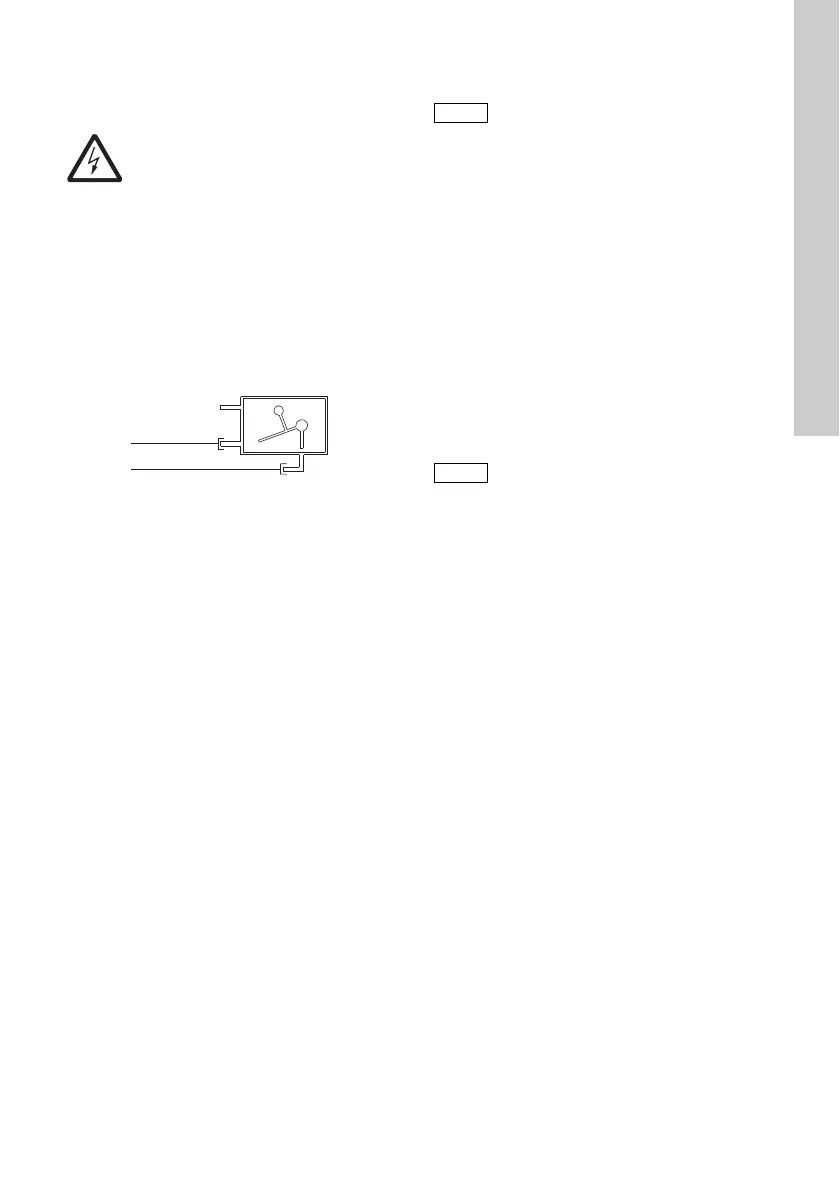
On delivery, the alarm cable is connected to
terminals COM1 (brown) and NO4 (blue) of the
safety overflow switch. See fig. 1.
Fig. 1 Wiring diagram
The alarm cable can be connected in two ways,
depending on application:
• Shutdown of condensate source
The safety overflow switch can be connected to a
Class-II low-voltage circuit.
To enable shutdown of the condensate source,
the COM1 and NO4 terminals of the safety
overflow switch must be connected in series with
the low-voltage thermostat circuit of the
condensate source.
• External alarm system
The COM1 and NC2 terminals can be used to
close a low-voltage alarm circuit.
To activate an alarm, the COM1 and NC2
terminals of the safety overflow switch must be
connected in series with the low-voltage alarm
circuit.
8. Startup
1. Check that all hoses and connections are tight.
2. Connect the power supply.
8.1 Checking the function
Pump operation
Press the manual test button.
Alarm
1. To ensure that the alarm level is reached,
squeeze the discharge hose (or close the
isolating valve, if fitted), and fill water into the
tank. The pump will be started via the float
switch.
2. Continue filling water into the tank until the safety
overflow switch is activated. If no external alarm
is connected to the Conlift, this function can be
checked by means of a multimeter.
3. Stop filling water into the tank and stop
squeezing the discharge hose. The alarm stops
(the switch opens). The pump continues
operating. When the stop level is reached, the
pump will stop.
After checking the function, push the inlet hose back
into the lifting station and let the condensate from the
boiler or air-conditioning system run into the tank
again.
Warning
Before starting work on the Conlift, switch
off the power supply and make sure that it
cannot be accidentally switched on.
Work on electric systems and components
must only be carried out by an authorised
electrician.
TM05 1152 2211
Brown
Blue
1 = COM1
2 = NC2
3 = NO4
Start up the Conlift in accordance with local
regulations and accepted codes of good
practice.
The safety overflow switch must be
activated before the water starts running
out of the Conlift.

 Loading...