Dismantling Procedures CR, CRN 32•45•64•90
58
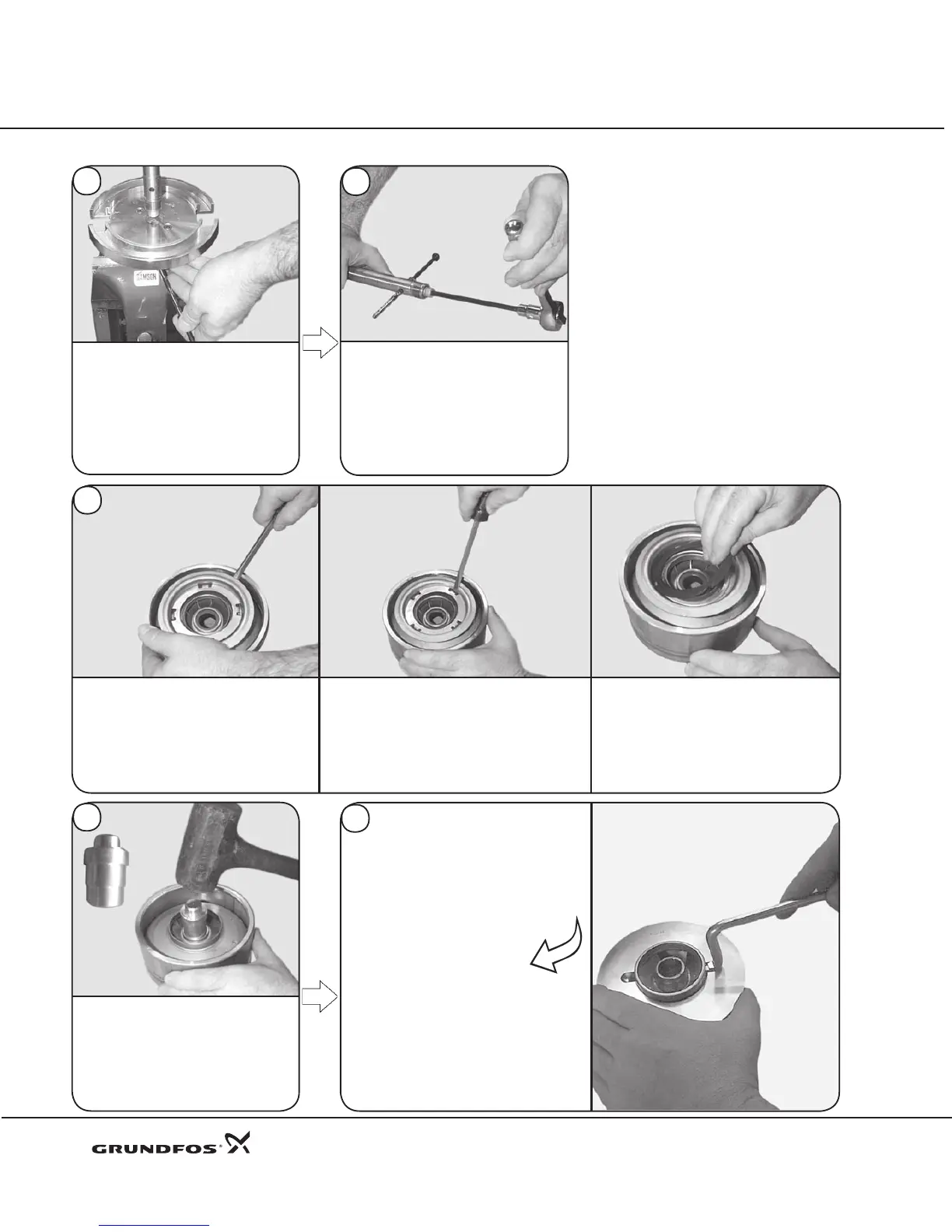
To remove the shaft from the
assembly/disassembly tool, remove
the holding pin from the shaft and
lift shaft out of tool.
After inspecting the parts, if further
disassembly is required, proceed to
the next steps.
59
Remove bearing from shaft. Remove
6 mm hex socket Allen Screw (Pos. 67),
locking washers (Pos. 66b), washer
(Pos. 66), and journal bearing (Pos. 47b).
Loosening the allen screw may require
use of the holding pin as a countering
device so the shaft does not spin.
Depending on wear, the Neck Ring (Pos. 45),
Retainer (Pos. 65), and Holder (Pos. 45a)
may need to be removed. Using a at bar,
pry these components out of the chambers
and base interface as a complete assembly.
If wear or damage is minor, the neck
ring may be replaced using a screw-
driver to twist and pry out the retainer.
Lift out the Neck Ring (Pos. 45).
60
To r e m o v e t h e C h a m b e r
Bearing (Pos. 47), Bearing Sleeve
(Pos. 47c), and Bearing Lock Ring
(Pos. 47d), place chamber upward
using the punch (00SV0015).
Drive the bearing downward.
61
62
If the Impeller Wear Ring (Pos. 49c) is
worn and the split cone nut/impeller
hub threads are not damaged, the
wear ring may be removed using
the app ropria te suppo rt t oo l,
• CR, CRN32 00SV0043
• CR, CRN45 00SV0044
• CR, CRN64 00SV0045
• CR, CRN90 00SV0046
along with the wear ring puller
(00SV0239) used to pry off the wear
ring. If the threads of the impeller hub are
damaged, a new impeller will be required.
10
Punch
 Loading...


