3. Dismantling and assembling the product
Parts are indicated by numbers and refer to the drawings in the
section on drawings.
Tools are indicated by letters and refer to the section on special
service tools.
Related information
7.3 Special service tools
7.5.1 Overview of drawings
7.5.2 Exploded views
7.5.3 Sectional views
3.1 Motor and coupling
3.1.1 Removal
1. Disconnect the power supply and remove the power cable.
2. Remove screws (7a) and coupling guards (7).
3. Remove screws (9) and coupling halves (10a). It may be
necessary to gently loosen the coupling halves with a plastic
hammer.
4. Remove the cylindrical pin (10) from the pump shaft (51).
5. Attach approved lifting equipment to the motor to prevent it from
falling before proceeding with any further dismantling. For
correct attachment of lifting equipment, see instructions supplied
with the pump.
6. Remove the screws (28), washers (32) and nuts (36).
7. Carefully lift the motor off the pump using approved lifting
equipment. For lifting the motor correctly, see the instructions
supplied with the pump.
3.1.2
Installation
1. Carefully lift the motor onto the motor stool (1a) using approved
lifting equipment.
2. Install the screws (28), washers (32) and nuts (36).
3. Lubricate and tighten the nuts (36) to the specified torque.
4. Install the cylindrical pin (10) in the pump shaft (51).
5. Install the coupling halves (10a).
6. Lubricate and cross-tighten the screws (9).
7. Install the coupling guards (7) and tighten the screws (7a).
Related information
7.1 Torques
7.2 Lubricants
3.2 Shaft seal, motor stool, pump head cover, sleeve
and chamber stack
3.2.1 Preparations
1. Remove the motor as described in the section on motor and
coupling removal.
2. Close the isolating valves, if fitted, to avoid draining the pipe
system.
3. Drain the pump by loosening the vent screw (18) and removing
the plugs (25) and O-rings (38).
Related information
3.1.1 Removal
3.2.2 Dismantling
1. Clean the end of the shaft (51) with a cloth.
2. If the shaft seal (105) is to be reused, remove any marks or
scratches on the shaft (51) by using service tool E together with
a piece of fine emery cloth.
3. Loosen the three set screws (113) of the shaft seal (105). Note
that the set screws must be loosened no more than 1/4 turn.
4. Loosen the shaft seal by using service tool A, together with
service tools O and P.
5. Carefully lift the shaft seal (105) off the shaft (51). Note that the
shaft seals fitted on pumps with ∅28 and ∅36 pump shafts can
be fitted with new wear parts. See the section on renewing shaft
seal wear parts.
6. Attach approved lifting equipment to the motor stool (1a) to
prevent it from falling before proceeding with any further
dismantling.
7. Remove nuts (36) and washers (66a).
8. Remove the motor stool (1a).
9. Remove the pump head cover (2). It may be necessary to
loosen it from the sleeve (55) using a plastic hammer.
10. Remove the O-ring (37) from the pump head cover.
11. Pull out the outlet part (44a) from the pump head cover (2).
12. CR pumps only: Remove the four screws (2d) and the brackets
(2c) from the pump head cover (2).
13. Fit service tool N on the pump sleeve (55). See the figure below.
TM071740
Service tool N fitted on sleeve (55)
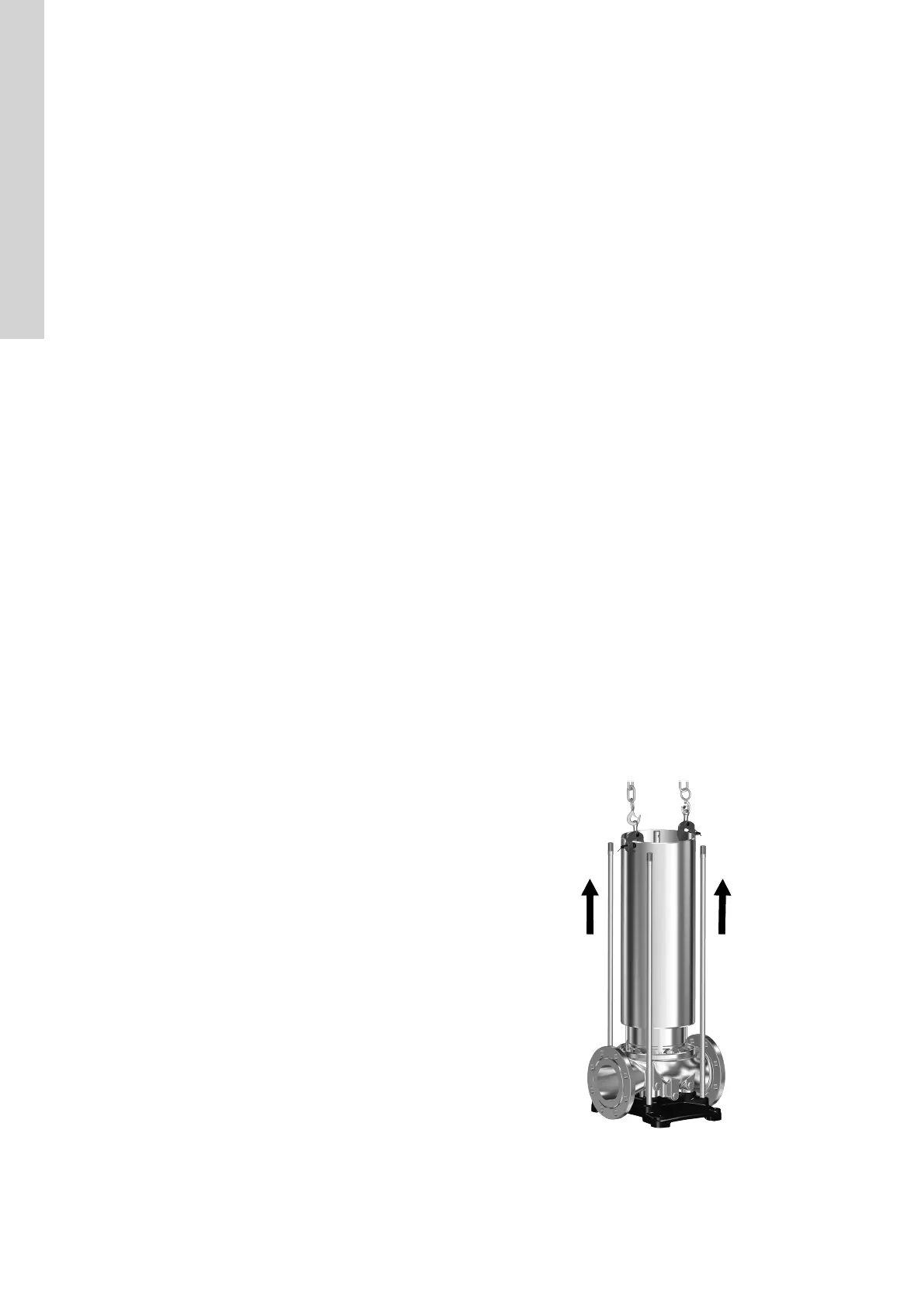
14. Attach approved lifting equipment to service tool N and lift the
sleeve (55) up and away from the chamber stack.
6
English (GB)

 Loading...


