15. Fit service tool B in the top of the pump shaft.
When handling the chamber stack, it is important to
pay close attention in order not to damage the thrust-
handling device (120), if fitted.
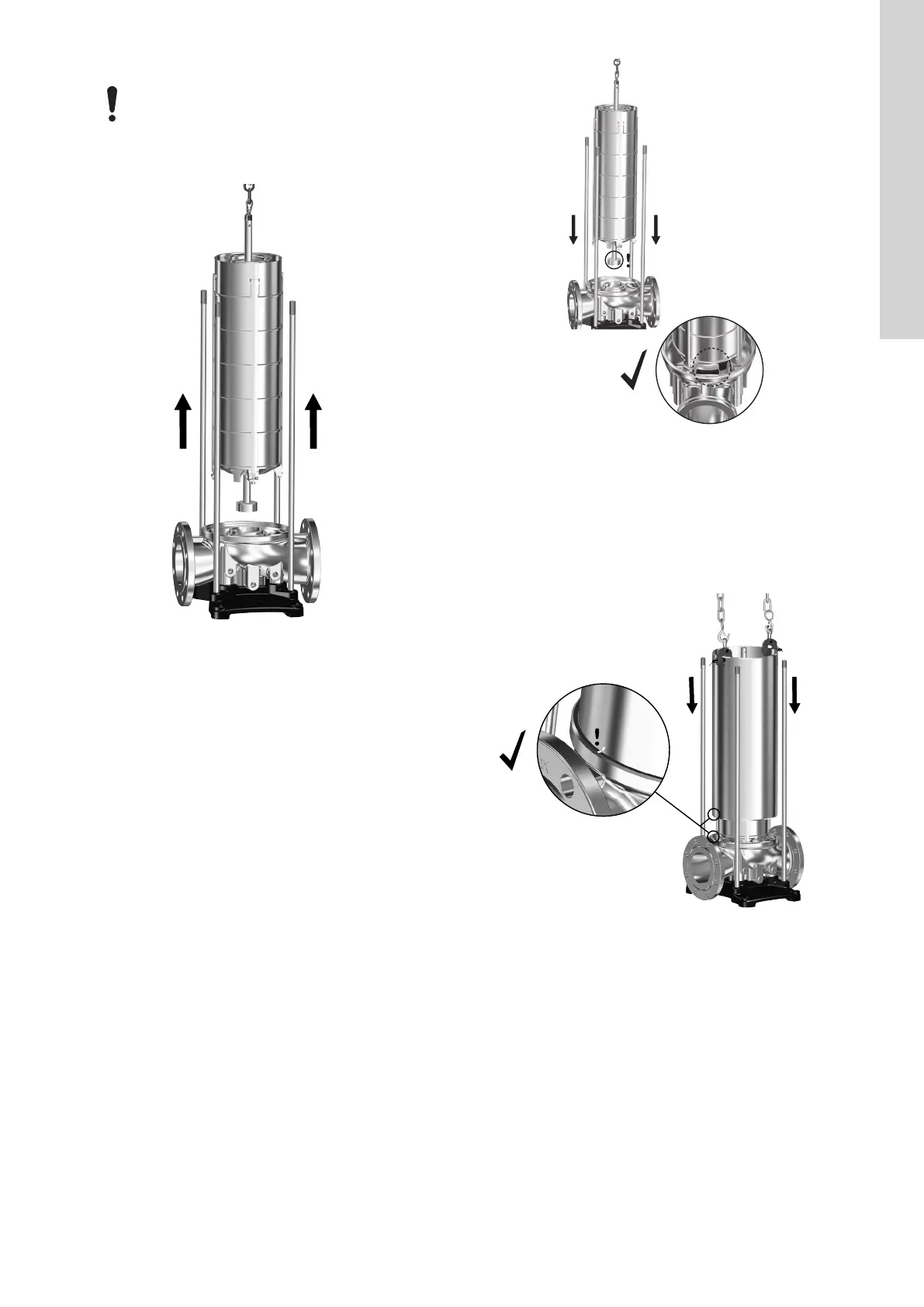
16. Attach approved lifting equipment to service tool B and lift up the
chamber stack.
TM071900
Lifting the chamber stack
17. Lay down the chamber stack in a fixed position so that it cannot
move.
18. Remove the O-ring (37) from the pump base.
Related information
6. Renewing shaft seal wear parts
7.3.1 Special tools
3.2.3
Assembly
1. Lubricate and install a new O-ring (37) in the pump base (6).
See the section on lubricants.
2. Carefully lift the chamber stack with approved lifting equipment
and lower it into the pump base.
Make sure to align the pump inlet part (44) with the tap in the
pump base (6). See the figure below.
TM071742
Aligning inlet part (44) in pump base (6)
3. Fit service tool N on the pump sleeve (55).
4. Attach approved lifting equipment to service tool N and lift the
sleeve (55) onto the pump base (6).
Make sure to align the sleeve (55) according to the alignment
marks on the sleeve (55) and on the pump base (6). Also
ensure that the sleeve (55) is pressed fully home in the pump
base (6).
TM070849
Aligning sleeve (55) in pump base (6)
5. Lubricate and install a new O-ring (37) in the pump head cover.
See the section on lubricants.
6. CR pumps only: Install the four screws (2d) and the brackets
(2c) in the pump head cover (2). See the section on torques.
7. Install the outlet part (44a) in the pump head cover (2).
7
English (GB)
 Loading...


