3
English (US)
2. Symbols used in this document
3. General information
These installation and operating instructions are a supplement to
installation and operating instructions for the corresponding
standard pumps CR, CRI, CRN, CRK, SPK, MTR, CHI and CM.
For instructions not mentioned specifically here, please see
installation and operating instructions for the standard pump.
4. General description
Grundfos E-pumps have standard motors with integrated
frequency converter. The pumps are for single-phase or three-
phase power supply connection.
4.1 Pumps without factory-fitted sensor
The pumps have a built-in PI controller and can be set up for an
external sensor enabling control of the following parameters:
• pressure
• differential pressure
• temperature
• differential temperature
•flow rate
• liquid level in a tank.
From factory, the pumps have been set to control mode
uncontrolled. The PI controller can be activated by means of
R100.
4.2 Pumps with pressure sensor
The pumps have a built-in PI controller and are set up with a
pressure sensor enabling control of the pump discharge
pressure.
The pumps are set to control mode controlled. The pumps are
typically used to hold a constant pressure in variable-demand
systems.
4.3 Settings
The description of settings apply both to pumps without factory-
fitted sensor and to pumps with a factory-fitted pressure sensor.
Setpoint
The desired setpoint can be set in three different ways:
• directly on the pump control panel
• via an input for external setpoint signal
• by means of Grundfos wireless remote control R100.
Other settings
All other settings can only be made by means of the R100.
Important parameters such as actual value of control parameter,
power consumption, etc. can be read via the R100.
If special or customized settings are required, use Grundfos PC
Tool E-products. Contact your local Grundfos company for more
information.
5. Mechanical installation
The pump must be secured to a solid foundation by means of
bolts through the holes in the flange or baseplate.
5.1 Motor cooling
To ensure sufficient cooling of motor and electronics, observe the
following requirements:
• Make sure that sufficient cooling air is available.
• Keep the temperature of the cooling air below 104 °F (40 °C).
• Keep cooling fins and fan blades clean.
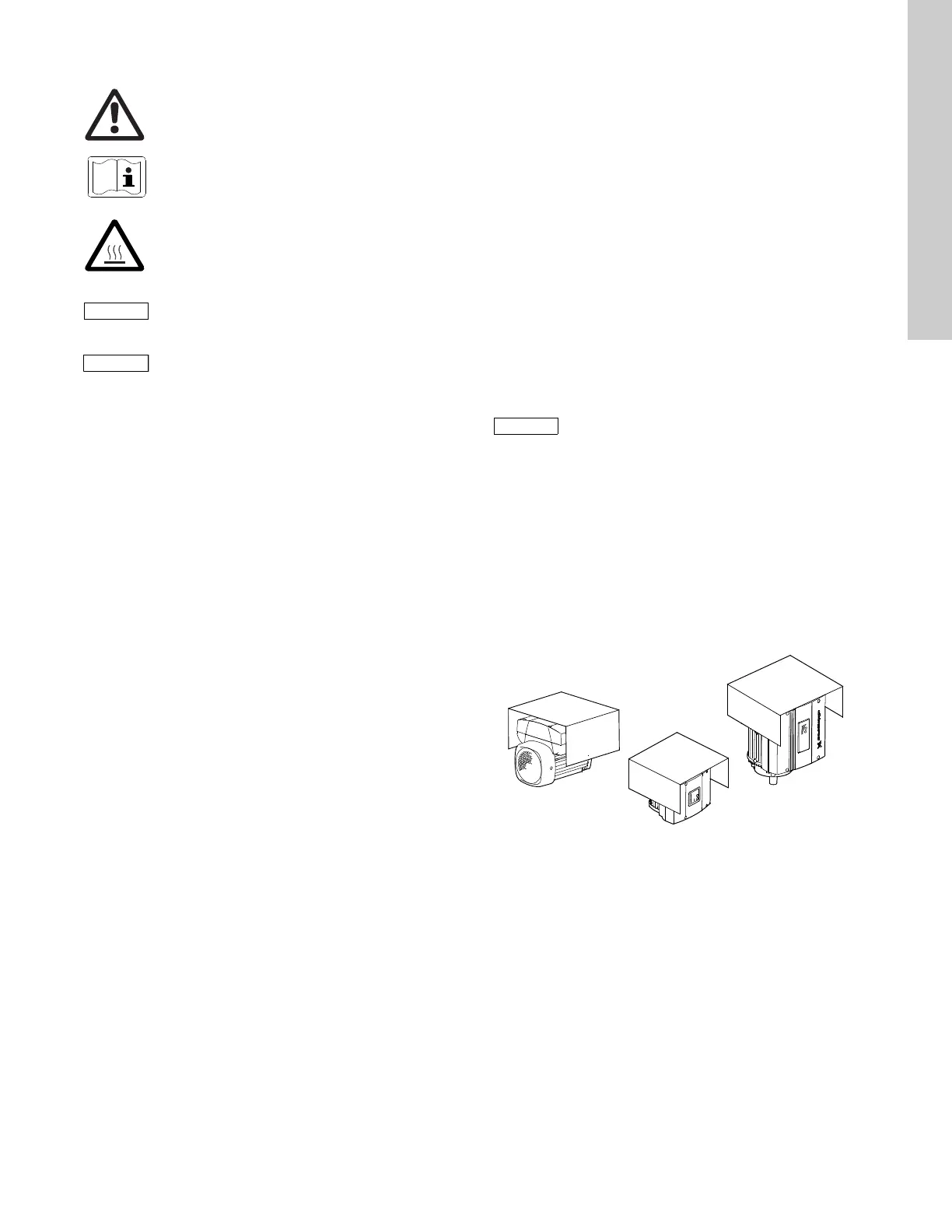
5.2 Outdoor installation
When installed outdoors, the pump must be provided with a
suitable cover to avoid condensation on the electronic
components. See fig. 1.
Fig. 1 Examples of covers
Remove the drain plug pointing downwards in order to avoid
moisture and water build-up inside the motor.
Vertically mounted pumps are IP55 after removal of the drain
plug. Horizontally mounted pumps change enclosure class to
IP54.
Warning
If these safety instructions are not observed, it
may result in personal injury!
Warning
The surface of the product may be so hot that
it may cause burns or personal injury.
If these safety instructions are not observed,
it may result in malfunction or damage to the
equipment.
Notes or instructions that make the job easier
and ensure safe operation.
In order to retain the UL/cUL approval, follow the
additional installation procedures on page 35.
TM00 8622 0101 - TM02 8514 0304
 Loading...