English (US)
4
6. Electrical connection
For description of how to connect E-pumps electrically, see the
following pages:
6.1 Single-phase pumps, page 4
6.2 Three-phase pumps, 1.5 - 10 hp, page 4
6.3 Three-phase pumps, 15-30 hp, page 6.
6.1 Single-phase pumps
6.1.1 Preparation
Before connecting the E-pump to the power supply, take the
issues illustrated in the figure below into consideration.
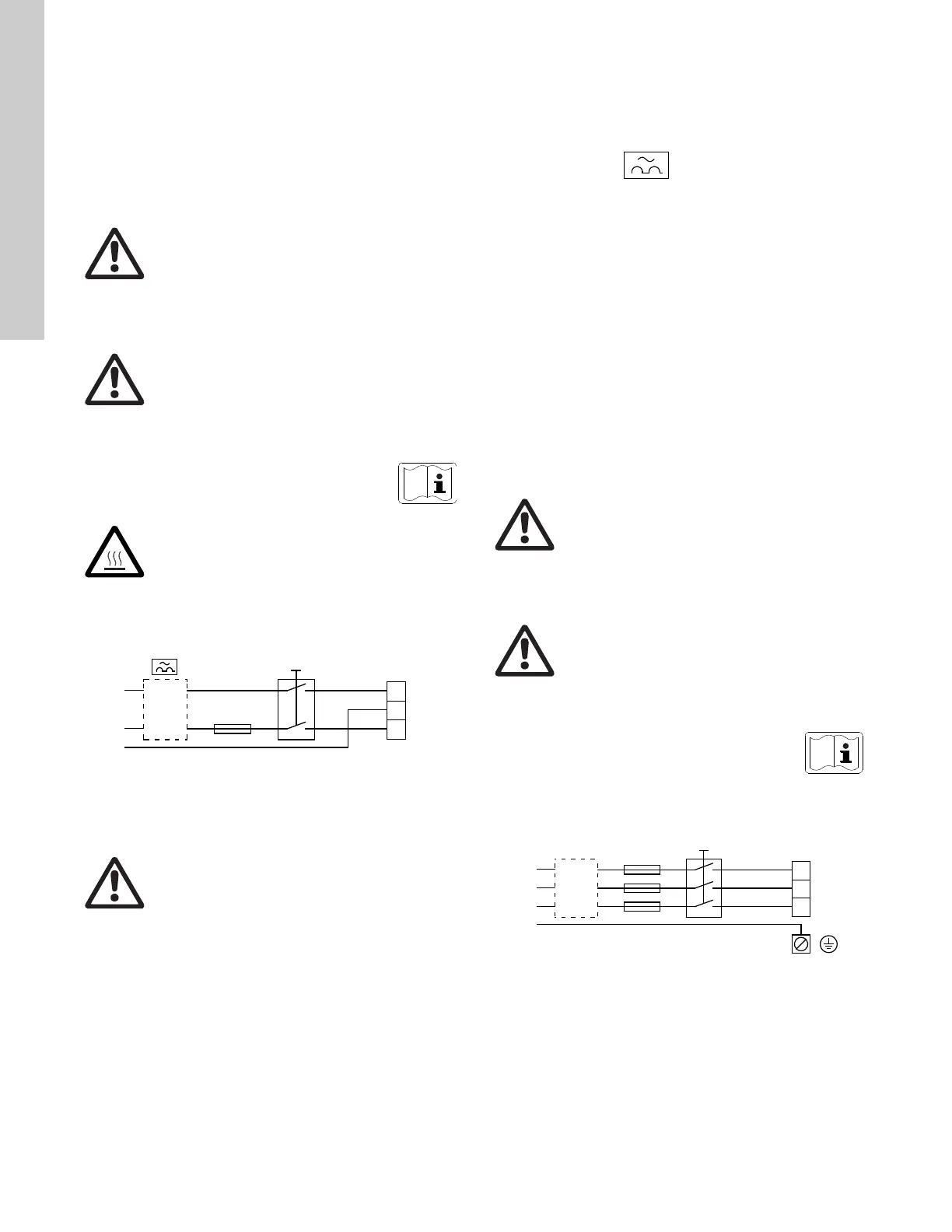
Fig. 2 Power supply-connected pump with power switch,
backup fuse, additional protection and protective
grounding
6.1.2 Protection against electric shock - indirect contact
Protective ground leads must always have a yellow/green (PE) or
yellow/green/blue (PEN) color marking.
6.1.3 Backup fuses
For recommended fuse sizes, see section 22.1 Supply voltage on
page 32.
6.1.4 Additional protection
If the pump is connected to an electric installation where an
ground leakage circuit breaker (ELCB) is used as additional
protection, the circuit breaker must be of a type marked with the
following symbol:
The total leakage current of all the electrical equipment in the
installation must be taken into account.
The leakage current of the motor in normal operation can be seen
in section 22.3 Leakage current on page 32.
During start and at asymmetrical supply systems, the leakage
current can be higher than normal and may cause the ELCB to
trip.
6.1.5 Motor protection
The pump requires no external motor protection. The motor
incorporates thermal protection against slow overloading and
blocking (IEC 34-11, TP 211).
6.1.6 Protection against voltage transients
The pump is protected against voltage transients by built-in
varistors between phase-neutral and phase-ground.
6.2 Three-phase pumps, 1.5 - 10 hp
6.2.1 Preparation
Before connecting the E-pump to the power supply, take the
issues illustrated in the figure below into consideration.
Fig. 3 Power supply-connected pump with power switch,
backup fuses, additional protection and protective
grounding
Warning
The user or the installer is responsible for the
installation of correct grounding and protection
according to current national and local
standards. All operations must be carried out by
qualified personnel.
Warning
Never make any connections in the pump
terminal box unless all electric supply circuits
have been switched off for at least 5 minutes.
Note for instance that the signal relay may be
connected to an external supply which is still
connected when the power supply is
disconnected.
The above warning is indicated on the motor terminal
box by this yellow label:
Warning
The surface of the terminal box may be above
158 °F (70 °C) when the pump is operating.
TM02 0792 0101
Warning
The pump must be grounded and protected
against indirect contact in accordance with
national regulations.
Warning
The user or the installer is responsible for the
installation of correct grounding and protection
according to current national and local
standards. All operations must be carried out by
qualified personnel.
Warning
Never make any connections in the pump
terminal box unless all electric supply circuits
have been switched off for at least 5 minutes.
Note for instance that the signal relay may be
connected to an external supply which is still
connected when the power supply is
disconnected.
The above warning is indicated on the motor terminal
box by this yellow label:
TM00 9270 4696

 Loading...