English (GB)
62
4. Fit the CIM module by aligning it with the three
plastic holders (fig. 62, A) and the connecting
plug (fig. 62, B). Press home the module using
your fingers.
Fig. 62 Fitting the CIM module
5. Fit and tighten securing screw (fig. 61, A) to 1.3
Nm.
6. Make the electrical connections to the CIM
module as described in the instructions delivered
with the module.
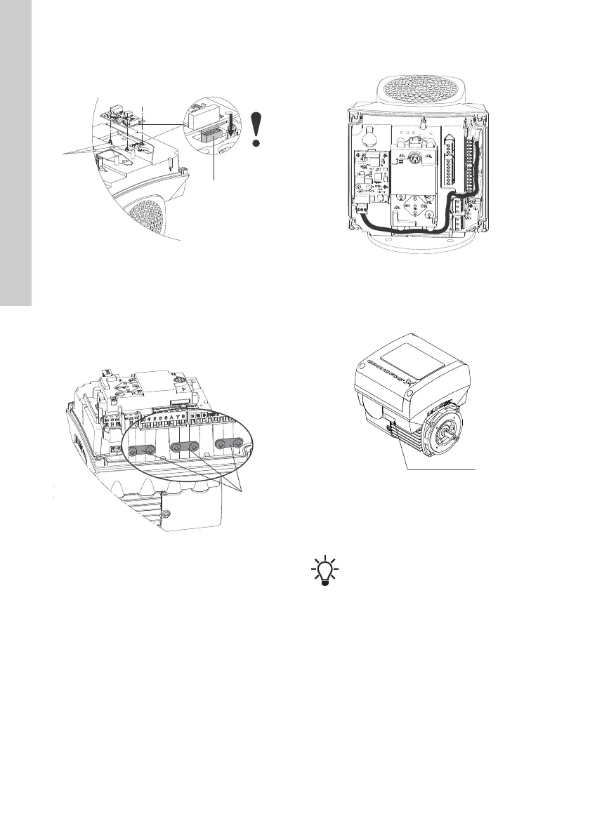
7. Connect the cable screens of the bus cables to
earth via one of the earth clamps (fig. 63, A).
Fig. 63 Connecting the cable screens to earth
8. Route the wires for the CIM module. See the
example in fig. 64.
Fig. 64 Example of wire routing
9. Fit the CIM cover.
10. If the CIM module is supplied with an FCC label,
then place this on the terminal box. See fig. 65.
Fig. 65 FCC label
11. Fit the terminal box cover (fig. 59, B) and
cross-tighten the four mounting screws (fig. 59,
A) to 6 Nm.
TM06 4083 1515TM06 4195 1615
TM06 4085 1515TM05 7028 0413
Make sure that the terminal box cover is
aligned with the control panel. See section
21. Changing the position of the control
panel.

 Loading...


