3
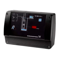
1. Constant-pressure control
1.1 Description
The system maintains a constant pressure within the
maximum pump performance in spite of a varying
water consumption.
Fig. 1 shows an example of an installation with con-
stant-pressure control.
Fig. 1
1.2 Function
The pressure is registered by means of the pressure
sensor, which transmits a signal to the CU 301. The
CU 301 adjusts the pump performance accordingly
by changing the pump speed.
Mains borne signalling:
The communication between the CU 301 and the
pump is effected via the power supply cable.
This communication principle is called mains borne
signalling (or power line communication). Using this
principle means that no additional cables to the
pump are required.
The communication of data is effected by means of a
high-frequency signal transmitted to the power sup-
ply cable and led into the electronics unit by means
of signal coils incorporated in the motor and the
CU 301 respectively.
Fig. 2 shows the principle of mains borne signalling
between the CU 301 and the pump.
Fig. 2
TM01 7862 4999
Pos. Description
1 CU 301
2 Diaphragm tank
3 Pressure sensor
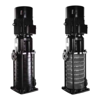
4 SQE pump
1
4
2
3
TM01 8495 1703
Pos. Description
1 Supply to the electronics
2 Signal coils
3 Capacitor
4
Electronics for the control of the com-
munication
5 On/off button
6 Sensor signal
7 Electricity supply
8 Communication signals
R 100
CU 301
1
5
2
4
3
6
7
8

 Loading...