8
Indication of pressure setting:
The system pressure set is indicated by a yellow
indicator light, which is permanently on.
Setting range: 2, 2.5 ... 5.0 bar.
Arrow-up button:
When this button is pressed, the system pressure
setting is increased in steps of 0.5 bar.
Arrow-down button:
When this button is pressed, the system pressure
setting is decreased in steps of 0.5 bar.
2.4 Button locking
The buttons on the CU 301 can be locked/unlocked
by pressing the two arrow buttons simultaneously for
5 seconds or via the R100 remote control.
Note: When the arrow buttons are used for locking,
the pressure setting may change.
Use the following procedure:
1. Set the pressure one step up.
2. Press the arrow-down button as the first one
when pressing the two buttons.
Fig. 11
When the buttons are locked, the indicator light is
permanently on, see fig. 11.
For further information, see section 5.3.7 Buttons on
CU 301.
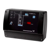
3. Alarm functions
The CU 301 continuously receives operating data
from the pump. The alarm functions indicated on the
CU 301 front are described in the following sections.
3.1 Service alarm
If one or more factory-set alarm values are exceed-
ed, the indicator light for service alarm is permanent-
ly on, see fig. 12.
Fig. 12
Possible alarms:
• Sensor defective.
• Overload.
• Overtemperature.
• Speed reduction.
• Voltage alarm.
• No contact to pump.
The possible alarms and how to identify them and
make the relevant corrections are described in sec-
tion 6.1 Service.
TM01 8330 4701
bar
5.0
4.5
4.0
3.5
3.0
2.5
2.0
TM01 8327 4701
bar
5.0
4.5
4.0
3.5
3.0
2.5
2.0

 Loading...