English (GB)
10
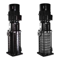
7.3.4 CVM component inspection
While the pump is disassembled, all components must be
inspected for wear, damage, deterioration or erosion.
• Check the wear of the bottom sleeve (2A) and sleeve bearing
(3). Replace them if they are loose, rough or noisy when
rotated.
• Check the balancing drum (9) and balance sleeve (10).
Replace them if they are seriously worn.
• If the sleeve bearing (3) and balance sleeve (10) need to be
replaced, remove them and tap new bearing and balance
sleeve into the right position with a plastic rod. Once in place
secure them with the locating screw.
• Check the radial runout of the shaft (1) at seal position. The
maximum allowed radial runout is 0.05 mm.
Order a replacement part with the name and position used in the
drawing on page 11.
7.3.5 Reassemble CVM pump
1. All parts must be clean before reassembly.
2. Place the key (16C) and balancing drum (9) on the pump shaft
(1).
3. Place the outlet case (21) and connection seat (19) on a flat
surface with the outlet stage (21) upwards.
4. Assemble the end-stage guide-vane (7B).
5. Push the shaft (1) with balance drum (9) into the outlet stage
(21) and support the pump shaft (1) with a support block to
ensure that the balancing drum (9) and balance sleeve (10)
are at the same horizontal level.
6. Assemble the key (16C), impeller (5) and middle sleeve (2B).
7. Assemble the middle stage (6).
8. Assemble the guide vane (7A).
9. Repeat assembling the key (16C), impeller (5), middle sleeve
(2B), middle stage (6), guide vane (7A), bottom sleeve (2A),
and then lock.
10. Insert the studs (22).
11. Assemble the inlet stage (23).
12. Preliminarily screw nuts (20) onto studs (22).
13. Reverse the hydraulic component and place the connection
seat (19) upwards.
14. Tighten the locating nut (20) in cross direction gradually.
15. Assemble the mechanical seal (11) and seal cap (12).
16. Assemble the motor (15).
17. Ensure that the pump shaft key (16B) and motor shaft key
(16A) are in the same direction.
18. Assemble a half coupling (13) with the keyway on the shaft.
19. Secure the washer (17) on the motor shaft end.
20. Turn the shaft coupling by hand and ensure it can rotate
freely.
21. Assemble the other coupling half.
22. Assemble the balance-pipe unit (8).
23. Assemble the coupling guard (14).
7.3.6 Reassemble CHM pump
1. All parts must be clean before reassembly.
2. Connect the balance hub (b4) on the pump shaft (f1).
3. Place the outlet casing (b2) and connection seat (a16) on a
flat surface with the outlet casing (b2) upwards.
4. Assemble the end-stage guide-vane (b3).
5. Push the shaft (f1) with balance hub (b4) into the outlet casing
(12) and support the pump shaft (f1) with a support block to
ensure that the balance hub (b4) and balance sleeve (b2) are
in the same horizontal level.
6. Assemble the impeller (f7), middle sleeve (c4) and key (d3).
7. Assemble the guide vane (d1).
8. Repeat steps 6 and 7 until all of the middle sleeve (c4) is built.
9. Assemble the inlet casing (b7) and connection seat (a23).
10. Assemble the studs (f5) and preliminarily screw nuts (f3) onto
the studs (f5).
11. Reverse the hydraulic component and make it level.
12. Tighten the nut (f3) in cross direction gradually.
13. Assemble the seal assembly (c1) and seal cap (c2).
14. Assemble the slinger (a10).
15. Install lip seal (a9) to the bearing frame (a7).
16. Assemble the bearing (a8) and round nut (a3), and then lock.
17. Assemble the seal assembly (c7) and seal cap (c9).
18. Assemble the slinger (a20).
19. Assemble the bearing (a19).
20. Assemble the bearing covers (a4) and (a17).
21. Assemble the balance-pipe unit (f8) and the coupling (5).
Pay attention to the direction of the inlet and outlet
flange. They must be fit for the installation
requirement.
The mechanical seal face must be clean.
Pay attention to the direction of the inlet and outlet
flange. They must be fit for the installation
requirement.
The mechanical seal face must be clean in both drive
end and non-drive end.