English (GB)
4
3.4 Mechanical installation
3.4.1 Pipes
• Make sure that both the inlet and outlet pipes are
independently supported and properly aligned so that no strain
is transmitted to the pump when flange bolts are tightened.
• Make sure the pipes are as straight as possible, so as to avoid
unnecessary bends and fittings. Where necessary, use 135 °
or long-sweep 90 ° pipe bends to decrease friction loss.
• Where flanged joints are used, make sure that the inside
diameters match properly and that mounting holes are aligned.
• Do not apply force to pipes when making any connections.
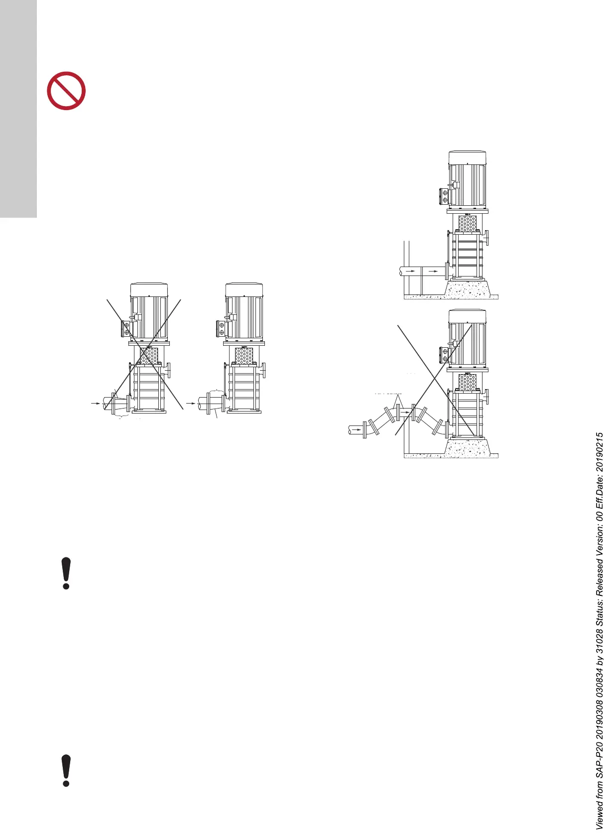
3.4.2 Inlet pipe
The inlet pipe must be installed in a manner that minimises
pressure loss and permits sufficient liquid flow into the pump
during starting and operation.
Observe the following precautions when installing the inlet pipe:
Fig. 2 Inlet pipe
• Run the inlet pipe as direct as possible, and ideally, make sure
the length is at least ten times the pipe diameter. A short inlet
pipe can be the same diameter as the inlet port. A long inlet
pipe must be one or two sizes larger than the inlet port,
depending on the length, and with a reducer between the pipe
and the inlet port.
• Use an eccentric reducer, with the tapered side down. See fig.
2.
• If possible, run a horizontal inlet line along an even gradient.
We recommend a gradual upward slope to the pump under
suction lift conditions, and a gradual downward slope under
positive inlet pressure conditions.
• Avoid any high points, such as pipe loops (see fig. 3), as this
may create air pockets and throttle the system or cause erratic
pumping.
• Install a gate valve in the inlet line to be able to isolate the
pump during shutdown and maintenance, and to facilitate
pump removal. Where two or more pumps are connected to
the same inlet line, install two gate valves to be able to isolate
each pump from the line.
• Always install gate or butterfly valves in positions that prevent
air pockets.
• During pumping operation, the valves on the inlet line must
always be fully open.
• Install properly sized pressure gauges in the tapped holes on
the pump inlet and outlet flanges.
Pressure gauges will enable the operator to monitor the pump
performance and determine whether the pump conforms to the
parameters of the performance curve. If cavitation, vapor
binding, or other unstable operating situations occur, the
pressure gauges will indicate wide fluctuation in the inlet and
outlet pressures.
Fig. 3 Air pocket prevention
3.4.3 Outlet pipe
• A short outlet pipe can be the same diameter as the pump
outlet port. A long outlet pipe must be one or two sizes larger
than the outlet port, depending on the length.
• It is best to use long horizontal outlet pipes.
• Install a gate valve near the outlet port to be able to isolate the
pump during shutdown and maintenance and to facilitate
pump removal.
• Any high points in the outlet pipe may entrap air or gas and
thus delay pump operation.
If non-return valves are used, close the outlet gate valve before
pump shutdown to prevent water hammer from occurring.
Do not let the pump support the pipes. Use pipe
hangers or other supports at proper intervals to
provide pipe support near the pump.
TM07 0878 0718
At no point must the diameter of the inlet pipe be
smaller than that of the pump inlet port.
Do not use globe valves, particularly when NPSH is
critical.
Air Pocket
Concentric
Reducer
Wrong
Concentric
Reducer
Right
This Is Down
Eccentric
Wrong
Right
Air pocket
This is down
Concentric
reducer
TM07 0879 0718