English (GB)
11
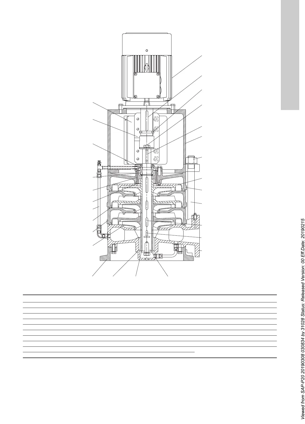
7.4 CVM, sectional drawing and parts list
Fig. 7 CVM pump construction
TM07 0859 0718
19
15
16A
17
16B
18
20
21
22
16C
23
14
13
12
11
10
9
8
7A
6
5
4 3 2A 1
7B
16'
Pos. Description Pos. Description Pos. Description
1 Shaft 9 Balancing drum 16D Sleeve key
2A Bottom sleeve 10 Balance sleeve 17 Washer
2B Middle
sleeve 11 Mechanical seal 18 Key
3 Sleeve bearing 12 Seal cap 19 Connection seat
4 Base 13 Coupling 20 Locknut
5 Impeller 14 Coupling guard 21 Outlet casing
6 Middle casing 15 Motor 22 Stud
7A Guide vane 16A Motor shaft key 23 Inlet casing
7B End-stage guide-vane 16B Pump shaft key
8 Balance-pipe unit 16C Impeller key